Variable traffic safety sign for displaying roadbed conditions in response to changes in temperature and humidity

a technology of traffic safety signs and roadbed conditions, applied in the direction of advertising, ways, construction, etc., can solve the problems of high possibility of freezing of the surface of the bridge section, traffic accidents, wet surfaces,

Active Publication Date: 2017-10-17
KOREA INST OF CIVIL ENG & BUILDING TECH
View PDF23 Cites 6 Cited by
  • Summary
  • Abstract
  • Description
  • Claims
  • Application Information

AI Technical Summary

Benefits of technology

[0030]The variable traffic safety sign for displaying roadbed conditions in response to changes in temperature and humidity according to the present invention may further include a light-reflecting paint formed of a light-reflecting material and applied onto an inner side of the general paint so that drivers driving on the road or bridge can secure visibility at...

Problems solved by technology

Generally, wet surfaces and freezing are main causes of traffic accidents caused due to vehicle slipping occurring on surfaces of roads.
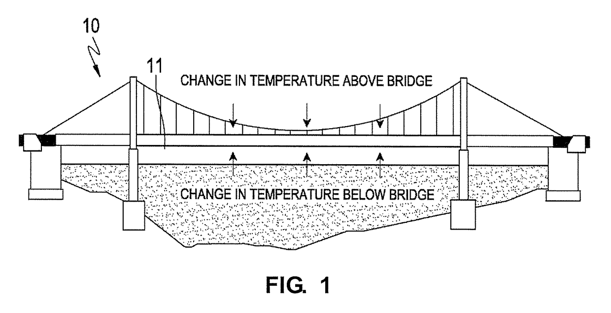
In particular, since a bottom surface of a bridge section is exposed to the air, a surface of the bridge section has a high possibility of being frozen, compared to a surface of a road having terrestrial heat.
As shown in FIG. 1, if the bottom surface of the bridge section is exposed to the air, pavement of the bridge has a high possibility of being frozen when the temperature drops below the freezing point, resulting in a further increased risk for accidents.
In particular, drivers may inadvertently mistake a wet road surface for shade at night when it is difficult to visually identify whether a surface of the road is wet or frozen due to the drivers' poor visibility, or when a thin freezing film referred to as ‘black ice’ occurs on the road, which results in a very high risk for accidents.
However, such traffic safety sign boards may not easily attract drivers since the traffic safety sign boards are always installed at fixed places...

Method used


Image

  • Variable traffic safety sign for displaying roadbed conditions in response to changes in temperature and humidity
  • Variable traffic safety sign for displaying roadbed conditions in response to changes in temperature and humidity
  • Variable traffic safety sign for displaying roadbed conditions in response to changes in temperature and humidity

Examples


Embodiment Construction

[0046]Hereinafter, exemplary embodiments of the present invention will be described in detail with reference to the accompanying drawings so that those of ordinary skill in the art can carry out the present invention. However, it should be understood that the present invention can be implemented in various foal's, and is not intended to limit the exemplary embodiments of the present invention. Also, in the drawings, descriptions of parts unrelated to the detailed description are omitted to clearly describe the present invention. Throughout the specification, like numbers refer to like elements, and descriptions of the same elements will be not reiterated.

[0047]Unless the context clearly indicates otherwise throughout the specification, it will be further understood that the terms “comprises,”“comprising,”“includes” and / or “including,” when used herein, specify the presence of stated features, integers, steps, operations, elements, components and / or groups thereof, but do not preclud...


PUM


Abstract

A variable traffic safety sign is useful in informing road users of the possibility of a surface of a road or bridge section being wet or frozen without using an additional external power source by exactly expressing freezing and wet roadbed conditions of the road or bridge section using a thermochromic paint and a humidity indicator paint, and also allowing road drivers to exactly recognize the roadbed conditions of the road or bridge section by displaying the freezing and wet roadbed conditions of the road or bridge section conditions in response to changes in temperature and humidity, respectively. Also, the variable traffic safety sign is readily applicable to structures such as a bridge crash barrier, a traffic safety sign board, a bridge guardrail, a road shoulder, and an inner part, entrance and exit of a tunnel.

Description

CROSS-REFERENCE TO RELATED APPLICATION[0001]This application claims priority to and the benefit of Korean Patent Application No. 10-2016-0150533, filed on Nov. 11, 2016, the disclosure of which is incorporated herein by reference in its entirety.BACKGROUND[0002]1. Field of the Invention[0003]The present invention relates to a variable traffic safety sign for roads and highways, and more particularly, to a variable traffic safety sign for variably displaying wet roadbed and freezing conditions of a road or bridge section in the form of a figure or characters using a thermochromic paint and a paint for a humidity indicator card (“HIC”) so as to inform road users of the possibility of a surface of the road or bridge section being wet or frozen.[0004]2. Discussion of Related Art[0005]Generally, wet surfaces and freezing are main causes of traffic accidents caused due to vehicle slipping occurring on surfaces of roads. In particular, since a bottom surface of a bridge section is exposed ...

Claims


Application Information

Patent Timeline
IPC IPC(8): E01F9/40G09F13/20G09F13/16G09F19/12G09F19/22G02F1/00
CPCE01F9/40G09F13/20G09F13/16G02F1/009G09F19/22G09F19/228G09F19/12G09F7/002G09F2007/1878E01F9/608E01F9/518E01F9/578E01F11/00
Inventor KIM, HYEONG YEOLPARK, JONG SUP
Owner KOREA INST OF CIVIL ENG & BUILDING TECH
Why Eureka
Try Eureka