Hot-air engine

a technology of hot air engine and hot air, which is applied in the direction of steam engine plants, rotary piston engines, solar thermal energy generation, etc., can solve the problems of poor mechanical efficiency, poor thermal efficiency, and relatively large physical size relative to power outpu

Active Publication Date: 2017-10-24
EVANS GLYN
View PDF12 Cites 3 Cited by
  • Summary
  • Abstract
  • Description
  • Claims
  • Application Information

AI Technical Summary

Benefits of technology

[0021]The hot-air engine preferably includes at least one third duct between the outlet of the working engine and the inlet of the compressor, thereby allowing the hot-air engine to operate in a closed cycle.

Problems solved by technology

Known hot-air engines suffer from numerous disadvantages, particularly when driven by relatively low temperature energy sources, including: poor mechanical efficiency; poor thermal efficiency; relatively large physical size relative to power output; and relatively high costs.

Method used


Image

  • Hot-air engine
  • Hot-air engine
  • Hot-air engine

Examples


first embodiment

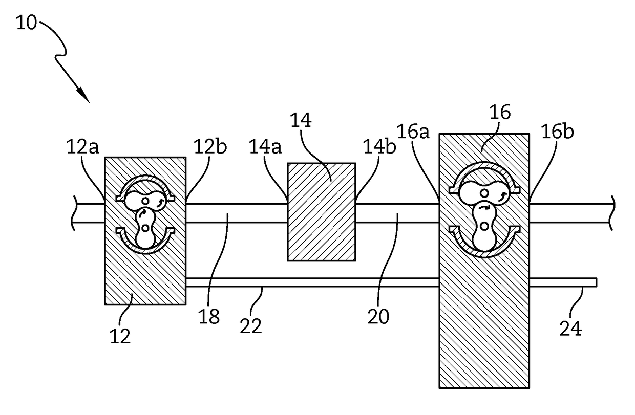
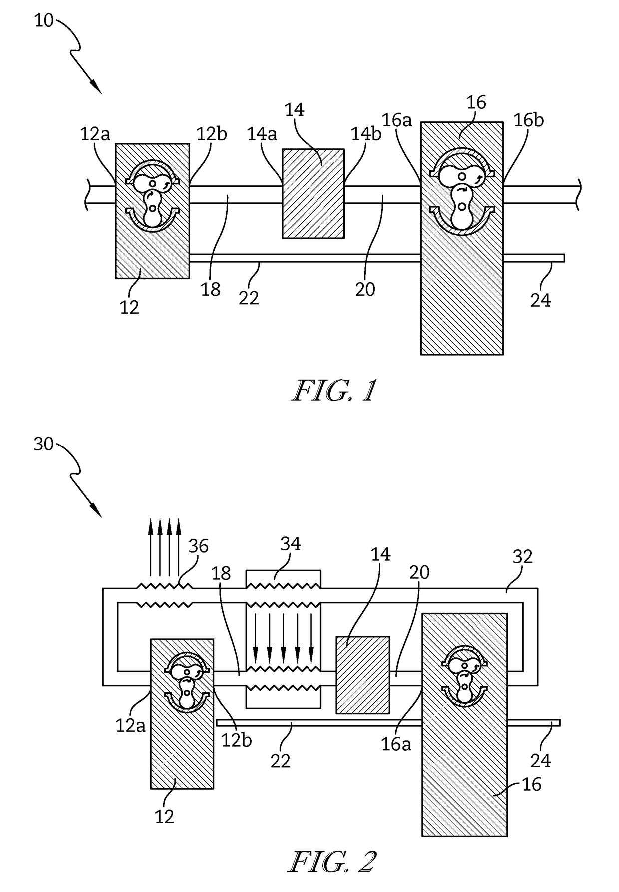
[0031]FIG. 1 schematically shows a hot-air engine 10 that includes a Roots type blower compressor 12, a heating chamber in the form of a furnace 14 and a Roots type blower displacement working engine 16. It will be understood by persons skilled in the art that the Roots type blower displacement working engine 16 is a Roots type blower pump or compressor being operated in the reverse direction to that used when operating as a pump or compressor.

[0032]The furnace 14 heats air using a process of external combustion. However, internal combustion is also able to used. The furnace 14 increases the pressure and volume of the air being supplied by the compressor 12, which then acts upon the working engine 16.

[0033]The capacity of the working engine 16 varies according to application. For a specific power output, the capacity of the working engine 16 is generally larger for lower temperature applications and smaller for higher temperature applications (such as automotive applications).

[0034]...

second embodiment

[0039]FIG. 2 schematically shows a hot-air engine 30. Like features to that described in relation to the hot-air engine 10 will be indicated with like reference numerals. The construction and operation of the hot-air engine 30 is similar to that of the hot-air engine 10 except that the heat engine 30 includes a third duct 32 connecting the outlet 16b of the working engine 16 to the inlet 12a of the compressor 12. The engine 30 also includes a heat exchanger 34, between a portion of the first duct 18 and a portion of the third duct 32. The engine 30 also includes a residual heat removal exchanger 36 in the third duct 32, upstream of the inlet 12a of the compressor 12.

[0040]The heat exchanger 34 improves thermal efficiency by increasing the temperature of the air supplied to the furnace 14. The use of the heat exchanger 34 permits the theoretical thermal efficiency of the hot-air engine 30 to rise from a maximum of about 28% to a maximum of about 72%, or greater if configured for high...

third embodiment

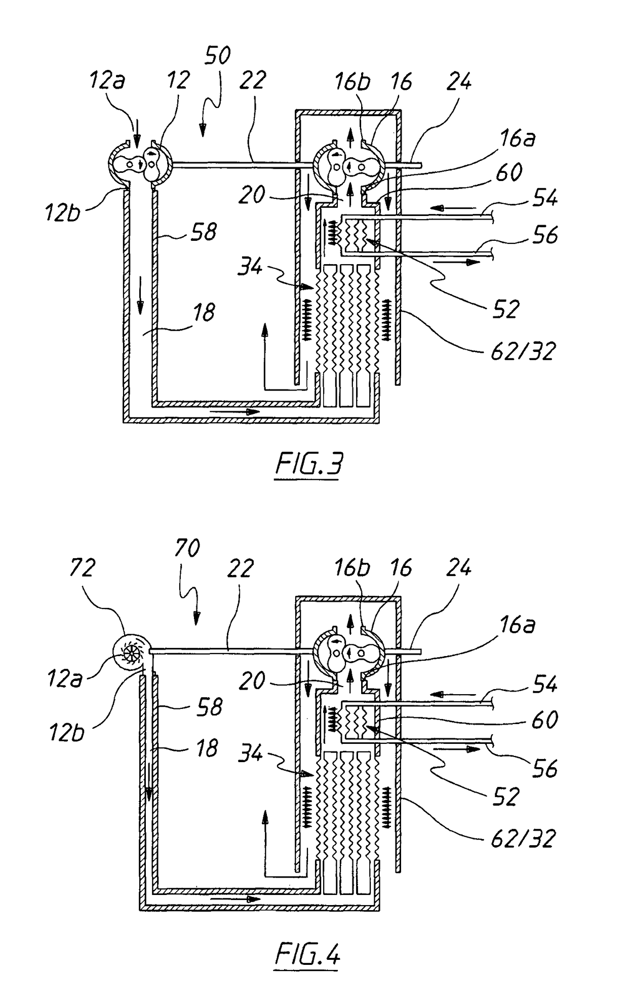
[0043]FIG. 3 schematically shows a hot-air engine 50. Like reference numerals to those used in describing features of earlier embodiments will again be used to indicate like features. In the hot-air engine 50, the furnace 14 is replaced by a heat exchanger 52 connected to a source of solar energy, such as one or more solar panels (not shown) via an inlet 54 and an outlet 56. If solar energy is not available, the heat exchanger 52 can be heated by stored solar thermal energy or other thermal energy sources.

[0044]In addition, the first duct 18, the second duct 20 and the third duct 32 are lagged with insulation 58, 60 and 62 respectively. This avoids heat losses and improves efficiency.

[0045]The hot-air engine 50 houses the heat exchanger 34, the heat exchanger 52 and the working engine 16 in one insulated housing so as to prevent heat loss. The hot-air engine 50 also advantageously arranges the heat exchangers 34 and 52 with a vertical temperature gradient. The hot-air engine 50 also...


PUM


Abstract

A hot-air engine (10) includes a compressor (12), a heating chamber (14), a rotary displacement type working engine (16) and a drive means (22). The compressor (12) has an inlet (12a) and an outlet (12b). The heating chamber (14) has an inlet (14a), in fluid communication with the outlet (12b) of the compressor (12), and an outlet (14b). The working engine (16) has an inlet (16a), in fluid communication with the outlet (14b) of the heating chamber (14), and an output shaft (16a). The drive means (22) connects the working engine (16) to the compressor (12) such that operation of the working engine (16) causes operation of the compressor (12).

Description

CROSS-REFERENCE TO RELATED APPLICATIONS[0001]This application is a national stage entry under 35 U.S.C. §371(b) of International Application No. PCT / AU2012 / 000383, filed Apr. 13, 2012, which claims the benefit of Australian Patent Application Serial No. 2011901682, filed May 6, 2011, the disclosures of which are hereby incorporated herein by reference.FIELD OF THE INVENTION[0002]The present invention relates to a hot-air engine for converting heat from external combustion, internal combustion, solar energy or other sources into mechanical work.[0003]The invention has been primarily developed for use in conversion of low to medium grade heat from various sources into mechanical energy. One particularly useful application is the generation of electricity from solar energy. However, it will be appreciated that the invention is not limited to this particular application and is also suitable for transport and other automotive uses, including hybrid vehicles.BACKGROUND OF THE INVENTION[00...

Claims


Application Information

Patent Timeline
Patent Type & Authority Patents(United States)
IPC IPC(8): F01K25/02F02G1/02F01C1/08F01C13/04F01C1/02F01C1/344
CPCF02G1/02F01C1/08F01C13/04Y02E10/46F01C1/344F02G2254/15F02G2254/30F01C1/02Y02E20/30Y02T10/12F02C1/04F02C1/10F02C3/055
Inventor EVANS, GLYN
Owner EVANS GLYN
Why Eureka
Try Eureka