Roller tube

a technology of roller tubes and rollers, applied in the field of roller tubes, can solve problems such as clear undesirable nois

Active Publication Date: 2017-11-07
LOUVER LITE LTD
View PDF94 Cites 9 Cited by
  • Summary
  • Abstract
  • Description
  • Claims
  • Application Information

AI Technical Summary

Benefits of technology

[0007]The sound channels are externally closed. This means that the sound channels do not include any openings to the exterior of the roller tube in use. On the basis that the sound channels extend longitudinally along at least part of the tube, they do not include an external longitudinal opening (e.g. an axial slot) which would allow sound to escape radially from the tube. Furthermore, in use, the opposed ends of the channels are closed by respective end caps to prevent sound escaping axially from the tube.
[0008]The sound channels reduce the extent to which the sound waves can be amplified or focussed by the curved outer wall of the tube. They also reduce the extent to which the sound waves within the tube can be transmitted or cause interference with each other. Moreover, the sound channels guide the sound waves away from the source of the sound (e.g. electric motor) and allow them to diminish via energy loss, for example as a result of internal reflections along the channels.
[0011]In an embodiment of the invention, each sound damping element includes at least one planar portion. Suitably, the planar portion is arranged to minimise sound generated or transmitted within the roller tube from reaching a portion of the curved outer wall of the tube and / or to disrupt reflected sound waves from the curved outer wall of the tube. Thus, the planar portion may be arranged at an angle to a radial reference plane. In other words, the planar portion subtends an angle with reference to a radial plane which is greater than 0° and less than 180°.
[0017]In an embodiment comprising four-sided closed cells around the entire internal circumference of the roller tube, the circumferential cells define a central core of the roller tube, wherein the defined central core has a regular polygonal shape in cross-section. In this embodiment, each side of the polygon is defined by the planar end wall of each cell. Thus, the number of cells around the circumference of the roller tube defines the number of sides that comprise the polygon shape of the core. For example, three closed four-sided cells around the circumference of the roller tube would result in a triangular shaped core, four cells would result in a square shaped core, five cells would result in a pentagonal shaped core, six cells would result in a hexagonal shaped core, seven cells would result in a heptagonal shaped core, eight cells would result in an octagonal shaped core and so on. The central core is still able to receive therein the further blind components, such as electric motors, etc. but the further blind components would then be surrounded by sound channels in the form of closed cells, which minimise the amount of sound audible outside of the roller tube.

Problems solved by technology

These further components can cause problems, especially in terms of unwanted noise.
Such noise is clearly undesirable.

Method used


Image

  • Roller tube
  • Roller tube
  • Roller tube

Examples


Embodiment Construction

[0047]For the avoidance of doubt, the skilled person will appreciate that in this specification, the terms “up”, “down”, “front”, “rear”, “upper”, “lower”, “width”, etc. refer to the orientation of the components as found in the example when installed for normal use as shown in the Figures.

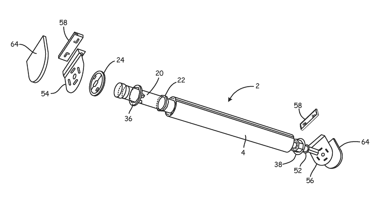
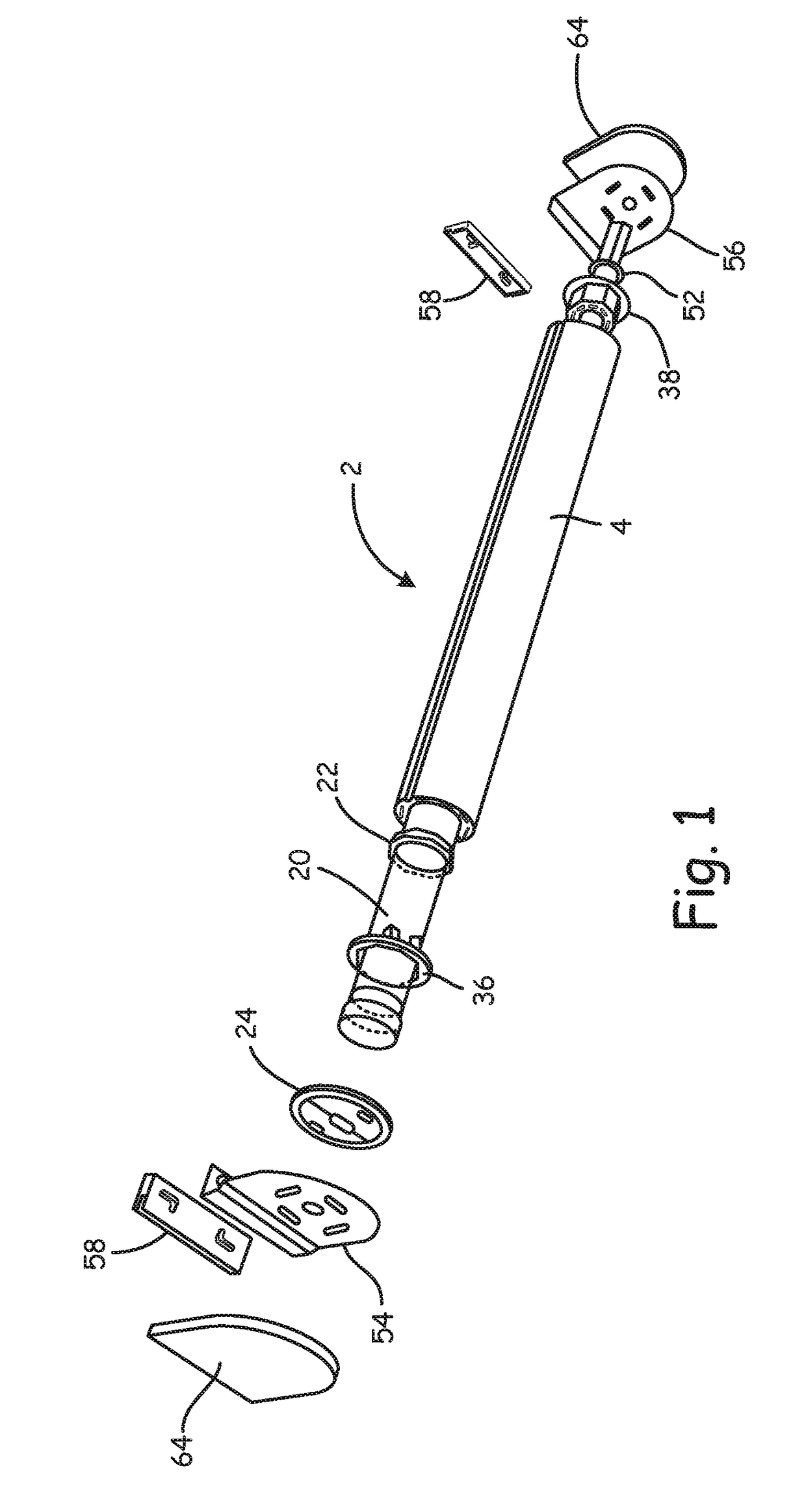
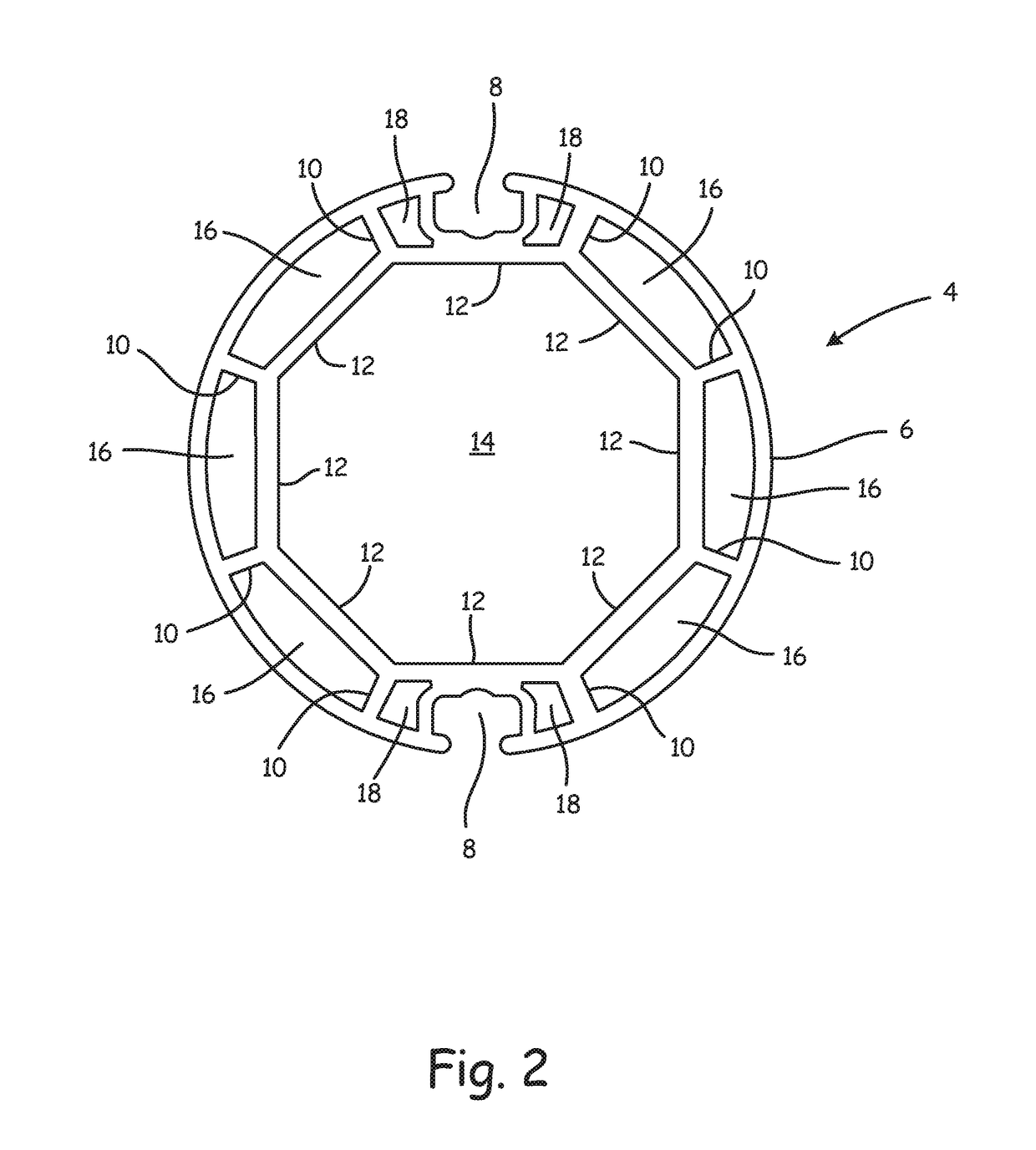
[0048]A roller blind assembly 2 is shown in FIG. 1. The assembly 2 comprises a roller tube 4 which is shown in more detail in FIG. 2. The roller tube 4 includes an outer tube wall 6 within which is defined a pair of opposed fabric receiving slots 8. In this embodiment, the two slots 8 are substantially identical. However, it will be appreciated that slots 8 having different dimensions may be incorporated.

[0049]Projecting radially inwards from the outer tube wall 6 are eight side wall elements 10 which are equally circumferentially spaced from each other. Each pair of adjacent side wall elements 10 are joined at their inwardly facing end by an end wall 12. The arrangement of end walls 12 provides t...


PUM


Abstract

A roller tube comprising a tube body which defines on its outwardly facing surface one or more blind substrate or shutter substrate receiving portions, wherein the tube body includes a plurality of sound damping elements located circumferentially around its inwardly facing surface, the sound damping elements extending longitudinally along at least part of the length of the tube body and defining a plurality of sound channels inside the tube.

Description

CROSS-REFERENCE TO RELATED APPLICATIONS[0001]This application is a continuation of U.S. patent application Ser. No. 14 / 380,816, filed on Aug. 25, 2014, and entitled “Roller Tube”, itself a United States national phase application under 35 U.S.C. §371 of International Application Serial No. PCT / GB2013 / 050467, filed on Feb. 25, 2013 and entitled “Roller Tube”, which claims priority to Great Britain Application Serial No. 1203153.0, filed on Feb. 23, 2012, the contents of each of which being incorporated herein in their entirety.BACKGROUND OF THE INVENTION[0002]The present invention relates to roller tubes and in particular to roller tubes for use with roller blinds or roller shutters. The roller tubes of the present invention include within the tube a plurality of sound damping elements.[0003]Roller tubes have been used for decades in blinds and shutters as a rotating element around which the operation of a blind or shutter may be based. Roller tubes are typically hollow cylinders and...

Claims


Application Information

Patent Timeline
Patent Type & Authority Patents(United States)
IPC IPC(8): E06B9/56E06B9/68E06B9/17E06B9/72E06B9/50E06B9/174E06B9/44
CPCE06B9/44E06B9/174E06B9/72E06B9/50E06B9/68E06B9/17076E06B9/42
Inventor BARNES, ANTONYGREENING, ANDREW
Owner LOUVER LITE LTD
Why Eureka
Try Eureka