
Liquid discharge head and liquid discharge apparatus

a liquid discharge head and liquid discharge technology, applied in the direction of printing, inking apparatus, etc., can solve the problems of reducing the discharge speed of liquid, affecting the quality of liquid discharge, and liquid cannot accurately reach the intended position on the recording medium, so as to achieve the effect of suppressing excessive temperature ris

Active Publication Date: 2017-11-14
CANON KK
View PDF10 Cites 3 Cited by
  • Summary
  • Abstract
  • Description
  • Claims
  • Application Information

AI Technical Summary

Benefits of technology

The patent is for a liquid discharge head and a liquid discharge apparatus that can circulate liquid without affecting the pressure or temperature. This helps to prevent the liquid from solidifying and clogging the system.

Problems solved by technology

In a case where the liquid to be discharged is a recording liquid in such a liquid discharge apparatus for example, volatile components in the recording liquid near discharge orifices may evaporate, and the concentration of color material increase accordingly, leading to irregular color in the recorded image.
There also are cases where the evaporation of the volatile components raises the viscosity of the liquid near the discharge orifices, which reduces the discharge speed of the liquid, and consequently the liquid cannot accurately reach the intended position on the recording medium.
Evaporation of volatile components can also cause clogging of the discharge orifices and pressure chambers or the like.
If the variation in pressure distribution or pressure is great, variation will also occur in discharge properties from the discharge orifices, and quality of the recording formed on the recording medium will deteriorate.
However, if the amount of liquid circulating through the pressure chambers is reduced, there are cases where high-temperature liquid that has passed through the pressure chambers and flowed downstream will back up toward the pressure chambers if the amount of liquid being discharged from the discharge orifices by driving of the recording elements suddenly increases.
This temperature change may change the discharge speed or discharge amount of the liquid, and affect recording quality.

Method used


Image

  • Liquid discharge head and liquid discharge apparatus
  • Liquid discharge head and liquid discharge apparatus
  • Liquid discharge head and liquid discharge apparatus

Examples


second example

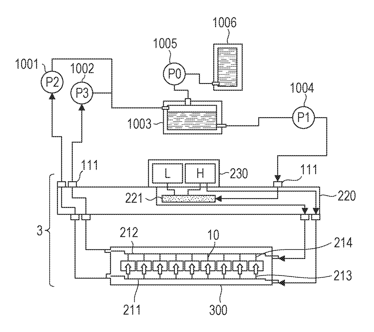
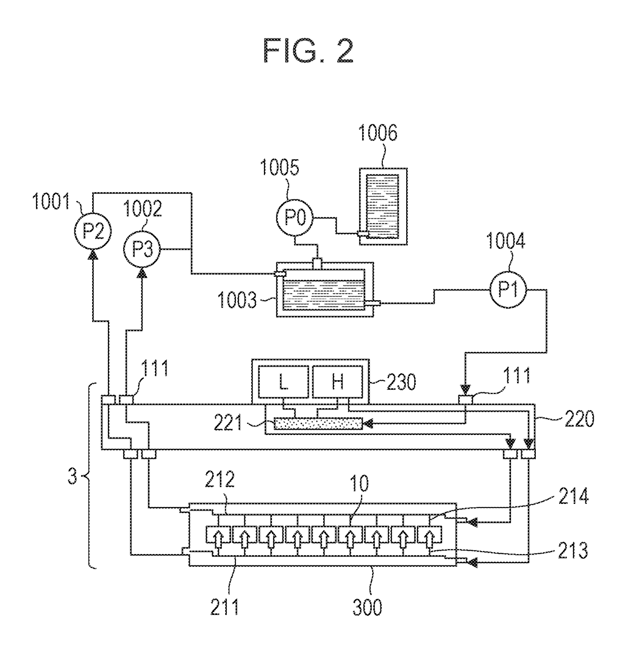
[0101]The second example takes note of the relationship between the composited flow resistance of the supply ports 17a and liquid supply channel 18, the composited flow resistance of the recovery ports 17b and the liquid recovery channel 19, the discharge amount Q, and the flow rate q of liquid circulating the through the pressure chambers 23 when not discharging. The flow rate of hot liquid backing up from the liquid recovery channel 19 is markedly reduced by these flows satisfying a later-described Expression (4). Note that the discharge amount Q here indicates the total sum of droplet amounts of droplets discharged from all discharge orifices 13 included in the liquid discharge head 3.

[0102]Based on Expression (1), the conditions for the flow rate of liquid supplied from the liquid recovery channel 19 to the pressure chambers 23 at the time of discharge to become substantially zero, i.e., the conditions for no backflow, are as in the following Expression (2).

[0103]q>Ri⁢⁢nRi⁢⁢n...


PUM


Abstract

A liquid discharge head includes a recording element board having a first face on which multiple recording elements are provided, and discharge orifices for the recording elements, where pressure chambers are formed for each recording element and liquid is discharged from discharge orifices. A liquid supply channel and a liquid recovery channel are provided in common to the plurality of recording elements, in a second face opposite to the recording element board from the first face. The pressure chambers are each made to communicate with the liquid supply channel and the liquid recovery channel by the supply ports and recovery ports respectively, and a flow from the liquid supply channel through the pressure chambers to the liquid recovery channel is generated. A composited flow resistance of the liquid recovery channel and recovery ports is greater than a composited flow resistance of the liquid supply channel and supply ports.

Description

BACKGROUND OF THE INVENTION[0001]Field of the Invention[0002]The present invention relates to a liquid discharge head and a liquid discharge apparatus that uses the liquid discharge head.[0003]Description of the Related Art[0004]A liquid discharge apparatus that records by discharging liquid onto a recording medium uses a liquid discharge head having a pressure chamber communicating with a discharge orifice and a recording element that provides energy for discharging to liquid within the pressure chamber. In inkjet recording apparatus, which is representative of liquid discharge apparatuses, discharges recording liquid from discharge orifices. The recording liquid is a color material such as dye or pigment contained in a medium. In a case where the liquid to be discharged is a recording liquid in such a liquid discharge apparatus for example, volatile components in the recording liquid near discharge orifices may evaporate, and the concentration of color material increase accordingl...

Claims


Application Information

Patent Timeline
Patent Type & Authority Patents(United States)
IPC IPC(8): B41J2/165B41J2/17B41J2/14B41J2/18
CPCB41J2/165B41J2/1408B41J2/18B41J2/14145B41J2/17B41J2/14032B41J2/14024B41J2/1404B41J2/14072B41J2202/12B41J2202/20B41J2202/21
Inventor MORIGUCHI, TAKUTOKARITA, SEIICHIROKOMAMIYA, YUMIOKUSHIMA, SHINGOYAMADA, KAZUHIRO
Owner CANON KK
Learn More