Electric compressor

a compressor and electric technology, applied in the direction of positive displacement liquid engines, piston pumps, lighting and heating apparatus, etc., can solve the problems of motors not being able to output the torque required for operating the compression mechanism, the torque required for the compression mechanism is high, and the magnetic flux density of the motor decreases, so as to prevent excessive temperature rise in the inverter, increase the heat generation of the inverter, and prevent the effect of torque reduction

Active Publication Date: 2021-02-02
DENSO CORP
View PDF13 Cites 0 Cited by
  • Summary
  • Abstract
  • Description
  • Claims
  • Application Information

AI Technical Summary

Benefits of technology

[0011]The present disclosure has been made in view of the above matter, and an object thereof is to provide an electric compressor capable of preventing a decrease in torque even when a motor is heated by a compressed high-temperature refrigerant and the temperature of the motor rises.
[0014]When the upper limit value of the driving current is changed to a value higher than the normal value, heat generation of the inverter increases. Thus, it is considered that the temperature of the inverter increases, which may make the operation unstable. However, in the electric compressor having the above configuration, the inverter is disposed at the position on the upstream side relative to the compression mechanism and the position cooled by the refrigerant. Thus, even when the heat generation amount of the inverter increases due to the change in the upper limit value, an excessive temperature rise in the inverter is prevented.
[0015]The present disclosure provides an electric compressor capable of preventing a decrease in torque even when a motor is heated by a compressed high-temperature refrigerant and the temperature of the motor rises.

Problems solved by technology

As a result, the magnetic flux density of the motor decreases, and the motor may become unable to output a torque required for operating the compression mechanism.
In particular, a torque required for the compression mechanism is high during a startup of the electric compressor.
Thus, when the electric compressor is restarted within a relatively short time after a stop of the electric compressor, a required torque may not be output due to a high temperature of the motor, and the electric compressor may fail to restart.

Method used


Image

  • Electric compressor
  • Electric compressor
  • Electric compressor

Examples


Embodiment Construction

[0030]Hereinbelow, embodiments will be described with reference to the accompanying drawings. Identical elements will be designated by the same reference sign throughout the drawings as far as possible to facilitate understanding of description, and redundant description will be omitted.

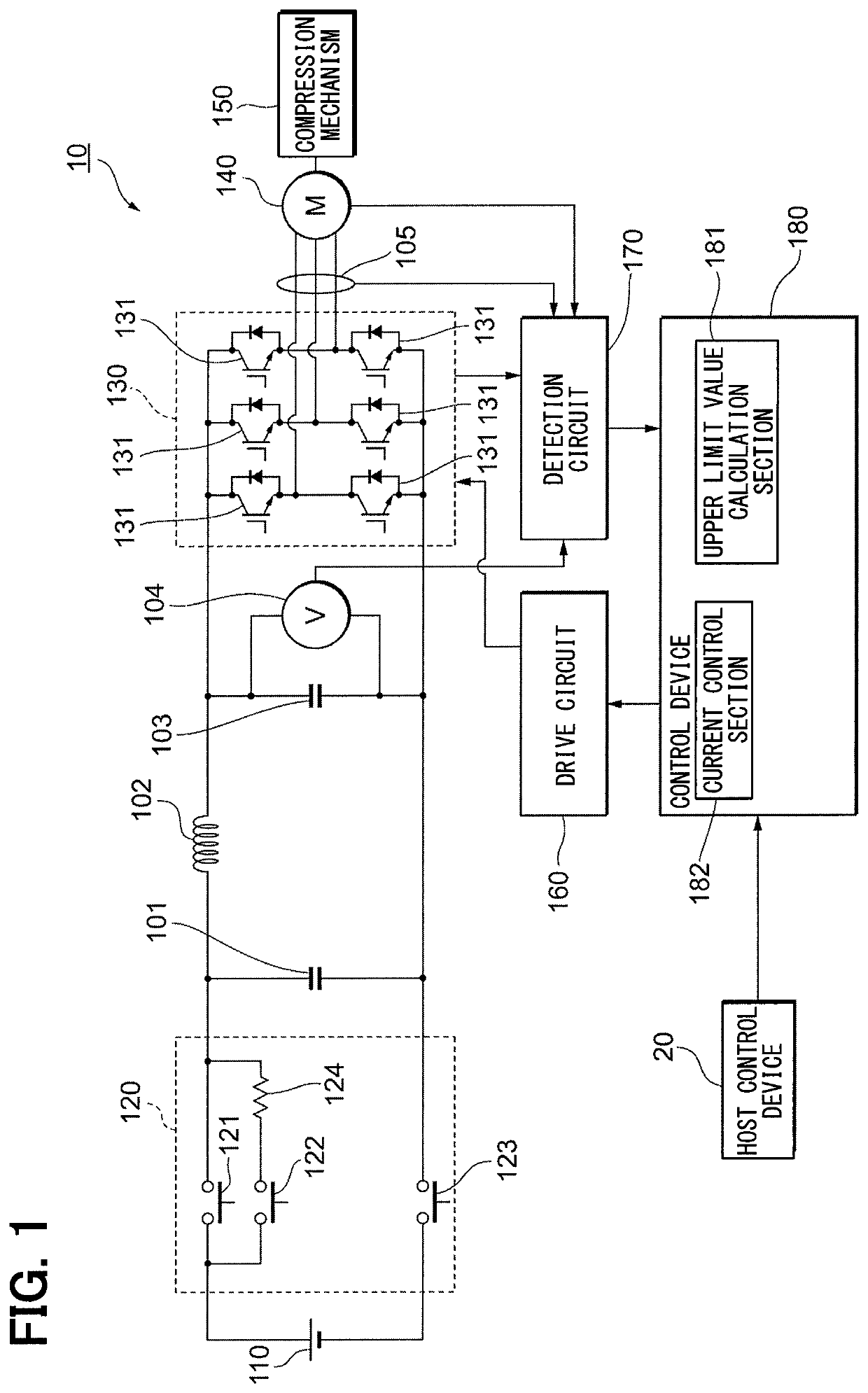
[0031]The configuration of an electric compressor 10 according to a first embodiment will be described with reference to FIG. 1. The electric compressor 10 is configured as an apparatus for circulating a refrigerant in a refrigeration cycle (not illustrated). The electric compressor 10 compresses, inside thereof, a low-temperature and low-pressure refrigerant supplied from an evaporator which is disposed on the upstream side to bring the refrigerant into a high-temperature and high-temperature state, and feeds the compressed refrigerant to a condenser which is disposed on the downstream side.

[0032]As schematically illustrated in FIG. 1, the electric compressor 10 includes a high-voltage battery 110, ...


PUM


Abstract

An inverter is disposed at a position on the upstream side relative to a compression mechanism along the flow of a refrigerant and the position cooled by the refrigerant. A motor is disposed at a position heated by the refrigerant compressed by the compression mechanism. A control device changes an upper limit value of a driving current supplied to the motor on the basis of at least one of first information relating to the temperature of the motor or second information relating to the temperature of the inverter.

Description

CROSS REFERENCE TO RELATED APPLICATIONS[0001]This application is a U.S. National Phase Application under 35 U.S.C. 371 of International Application No. PCT / JP2016 / 081606 filed on Oct. 25, 2016 and published in Japanese as WO 2017 / 082045 A1 on May 18, 2017. This application is based on and claims the benefits of priority from Japanese Patent Application No. 2015-221763 filed on Nov. 12, 2015. The entire disclosures of all of the above applications are incorporated herein by reference.TECHNICAL FIELD[0002]The present disclosure relates to an electric compressor that compresses and feeds out a refrigerant supplied to the electric compressor.BACKGROUND ART[0003]An electric compressor operates a compression mechanism by a driving force of a motor to compress a supplied refrigerant and feed the compressed refrigerant to the outside. The electric compressor having such a configuration is used as an apparatus for circulating a refrigerant in a refrigeration cycle.[0004]An electric compresso...

Claims


Application Information

Patent Timeline
Patent Type & Authority Patents(United States)
IPC IPC(8): F04B49/06F04B35/04F04B49/10
CPCF04B49/06F04B35/04F04B49/10F04B2203/0201F04C2240/808F25B2600/021F04C2240/403F25B49/025F04C18/0215F04B2203/0209F04C28/08F04C23/008F04C2270/19
Inventor SAKAI, KOJI
Owner DENSO CORP
Why Eureka
Try Eureka