Chuck and clamp with quick change function

a technology of function and chuck, applied in the field of chucks, can solve the problems of resource-intensive both methods, and achieve the effects of easy and rapid installation, rapid change of clamps, and special rapid installation on chucks

Inactive Publication Date: 2017-11-21
ROHM GMBH
View PDF10 Cites 0 Cited by
  • Summary
  • Abstract
  • Description
  • Claims
  • Application Information

AI Technical Summary

Benefits of technology

[0006]It is therefore an object of the present invention to provide a chuck with which rapid changing of a clamp is made possible. At the same time, the chuck should be implemented such that even different clamps with different locking systems can be installed easily and rapidly. Moreover, the invention provides a clamp with a locking system that can be installed on a chuck especially rapidly.

Problems solved by technology

Both methods are resource-intensive due to the complicated alignment of the clamp to the chuck prior to installation, and also due to the necessity to use special tools.

Method used


Image

  • Chuck and clamp with quick change function
  • Chuck and clamp with quick change function
  • Chuck and clamp with quick change function

Examples


Embodiment Construction

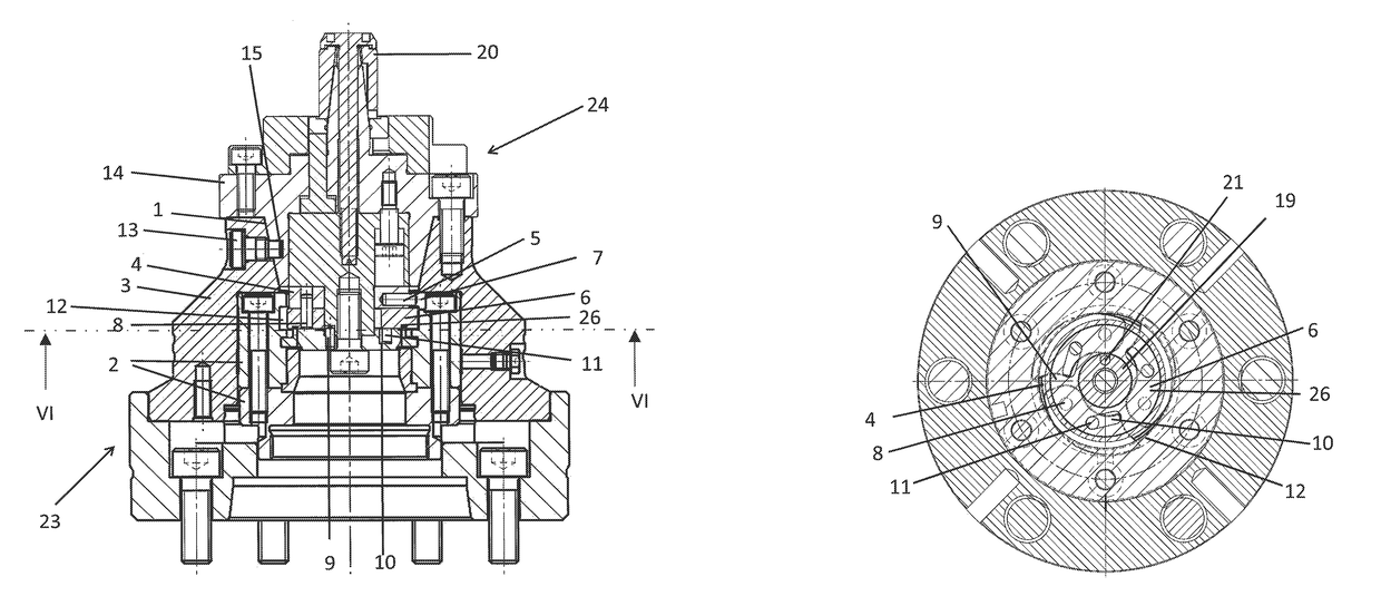
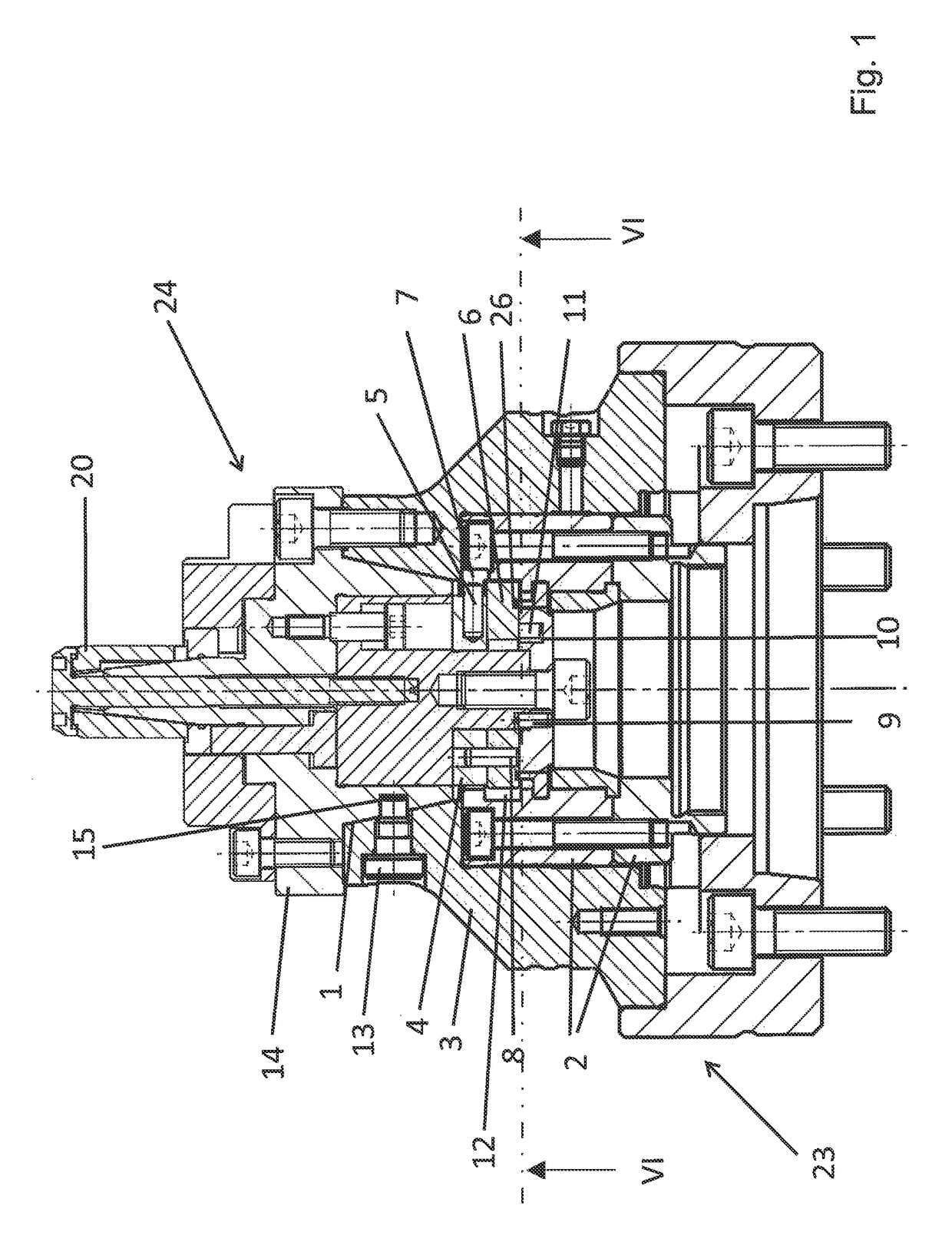
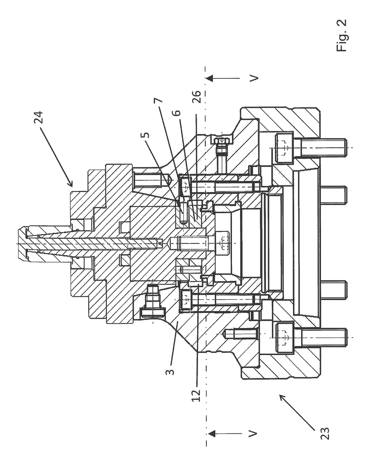
[0031]FIG. 9 shows a clamp 24, in this case a mandrel, which can be secured to a chuck 23 and serves to chuck a tool. The clamp 24 has a conically shaped clamp body 14, a chucking element 20, in this case a mandrel, and a locking unit 25. Formed in the clamp body is a guide slot 15 that extends axially parallel to the longitudinal axis of the clamp 24 in a translation region 15.1, and is adjoined at right angles by a rotation region 15.2. The locking unit 25 is carried by a pivot body 19 and having a cover 9, a segment 6, and a rotary disk 4. A blocking element 5 in the form of a peg projects laterally from the rotary disk. The rotary disk 4 is connected to the segment 6 by a bearing element 8. In the exemplary embodiment shown, as depicted in FIG. 10, the segment 6 is composed of three latches 26 that can pivot outward. As is evident from FIG. 5, the latches 26 are rounded at one end and have a latch receptacle at the other end that is rounded in a manner matched thereto for a spac...


PUM


Abstract

A chuck with a chuck body having a guide opening and an actuating element, and with at least one interchangeable clamp that can be inserted into the guide opening. The clamp has associated therewith a rotary disk with a blocking element that secures the rotary disk against rotation relative to the chuck body during insertion of the clamp into the guide opening. This makes it possible that, upon a rotation of the clamp about the longitudinal axis in the guide opening, a segment can be displaced outward toward the chuck body by the rotation relative to the rotary disk, via which the clamp is detachably secured on the chuck body. A clamp with a clamp body, a pivot body located in the clamp body, and a chucking element is also provided. The clamp has, at the opposite end of the clamping element, a locking unit that carries the pivot body.

Description

[0001]This nonprovisional application claims priority under 35 U.S.C. §119(a) to German Patent Application No. 10 2014 109 546.4, which was filed in Germany on Jul. 8, 2014, and which is herein incorporated by reference.BACKGROUND OF THE INVENTION[0002]Field of the Invention[0003]The present invention relates to a chuck with a chuck body having a guide opening and an actuating element, and with at least one interchangeable clamp that can be inserted into the guide opening. In addition, the invention relates to a clamp with a clamp body, a pivot body located in the clamp body, and a chucking element.[0004]Description of the Background Art[0005]Chucks are known in practice, and are offered by the applicant under the designation KZZT. A Clamp, which can be a mandrel, is also known in practice, and are offered by the applicant under the designation ABSIS. In order to change the clamp, it is normally necessary to release the tension linkage from the drawbar using a special wrench. The ot...

Claims


Application Information

Patent Timeline
Patent Type & Authority Patents(United States)
IPC IPC(8): B23B31/39B23B31/40B23B31/26B23B31/20B23B31/113B23B31/42
CPCB23B31/4033B23B31/39B23B31/207B23B31/26Y10T279/17888B23B31/42B23B2231/2078B23B2240/04Y10T279/17863B23B31/113B23B31/10B23B31/102B23B31/2072
Inventor DERHEIM, WALDEMAR
Owner ROHM GMBH
Why Eureka
Try Eureka