
Multilayered substrate and method of manufacturing the same

a technology of multi-layered substrates and manufacturing methods, applied in the direction of conductive pattern formation, circuit masks, printed element electric connection formation, etc., can solve the problems of increasing the possibility of unpredictable deformation of multi-layered substrates, and increasing the difficulty of achieving interlayer alignmen

Active Publication Date: 2017-11-28
SAMSUNG ELECTRO MECHANICS CO LTD
View PDF26 Cites 5 Cited by
  • Summary
  • Abstract
  • Description
  • Claims
  • Application Information

AI Technical Summary

Benefits of technology

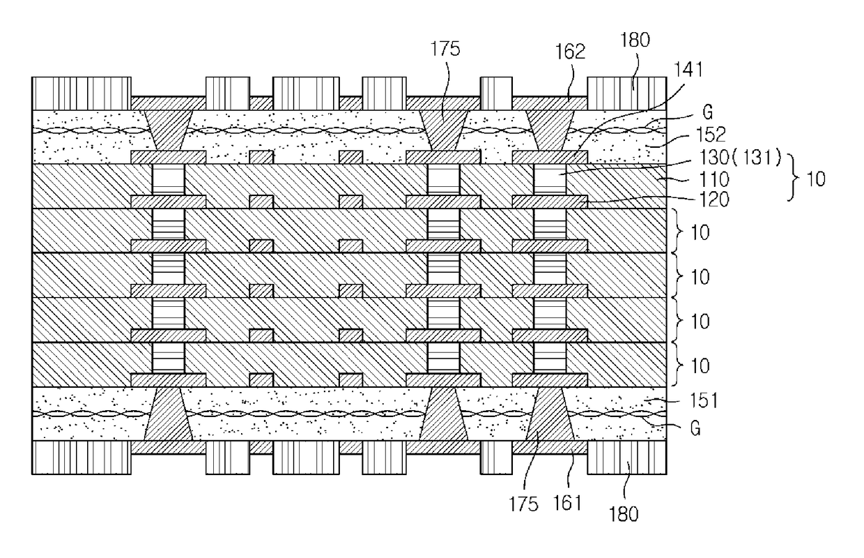
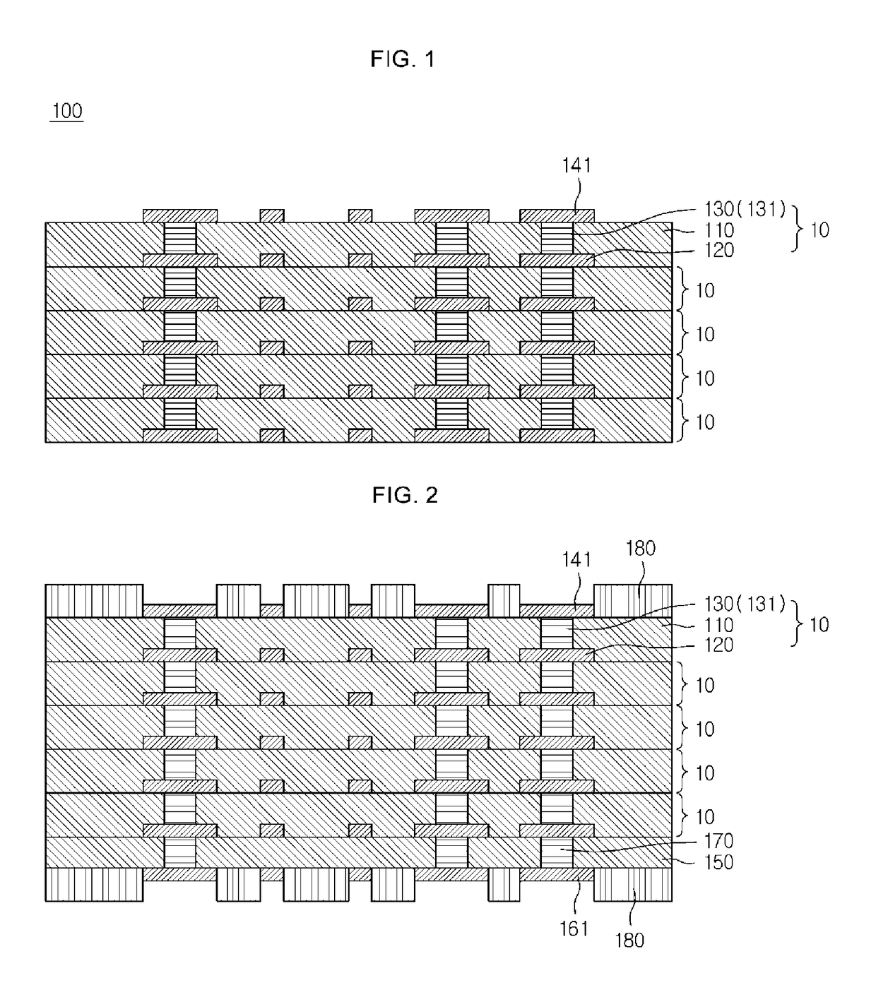
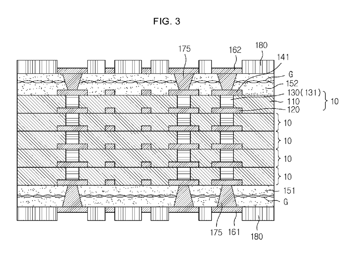
The patent describes a method of manufacturing a multilayered substrate by laminating unit substrates together. The unit substrates are formed by forming a conductive pattern on a carrier, adding a photosensitive insulating layer to cover the conductive pattern, and removing the carrier. The method involves forming bumps on the conductive pattern, with the bumps including a solder layer. The bumps can be formed by disposing a mask with a hole and inserting solder paste into the hole. The method can also involve laminating a support layer on top of the photosensitive insulating layer, patterning the first metal layer, and adding a second insulating layer to cover the first metal layer. The multilayered substrate can also include a first metal pattern, a second insulating layer, a second metal pattern, and a via connecting the conductive pattern with the second metal pattern. The technical effects of the patent include improved manufacturing efficiency and reduced costs for multilayered substrates.

Problems solved by technology

During these laminating processes, heat is applied to the portions of the multilayered substrate that are already laminated, increasing the possibility that unpredictable deformations may occur in the multilayered substrate.
With an increase in the number of layers required to implement the multilayered substrate, the probability of deformation increases, escalating the difficulty of achieving interlayer alignment.

Method used


Image

  • Multilayered substrate and method of manufacturing the same
  • Multilayered substrate and method of manufacturing the same
  • Multilayered substrate and method of manufacturing the same

Examples


Embodiment Construction

[0056]The following detailed description is provided to assist the reader in gaining a comprehensive understanding of the methods, apparatuses, and / or systems described herein. However, various changes, modifications, and equivalents of the methods, apparatuses, and / or systems described herein will be apparent to one of ordinary skill in the art. The sequences of operations described herein are merely examples, and are not limited to those set forth herein, but may be changed as will be apparent to one of ordinary skill in the art, with the exception of operations necessarily occurring in a certain order. Also, descriptions of functions and constructions that are well known to one of ordinary skill in the art may be omitted for increased clarity and conciseness.

[0057]The features described herein may be embodied in different forms, and are not to be construed as being limited to the examples described herein. Rather, the examples described herein have been provided so that this disc...


PUM


Abstract

A multilayered substrate includes unit substrates laminated in a direction of thickness thereof, and the unit substrates include a photosensitive insulating layer, a conductive pattern disposed in the photosensitive insulating layer, and a bump penetrating into the photosensitive insulating layer and providing an interlayer connection to the conductive pattern.

Description

CROSS-REFERENCE TO RELATED APPLICATIONS[0001]This application claims the benefit under 35 USC 119(a) of Korean Patent Application Nos. 10-2015-0092257, 10-2016-0041222 and 10-2016-0081510, respectively filed on Jun. 29, 2015, Apr. 4, 2016 and Jun. 29, 2016, in the Korean Intellectual Property Office, the entire disclosure of all of which are incorporated herein by reference.BACKGROUND[0002]1. Field[0003]The following description relates to a multilayered substrate and a method of manufacturing the multilayered substrate.[0004]2. Description of Related Art[0005]When a multilayered substrate is manufactured, a plurality of build-up layers are successively laminated on a core substrate. Accordingly, the number of laminating processes increases in proportion to the number of layers in the multilayered substrate. During these laminating processes, heat is applied to the portions of the multilayered substrate that are already laminated, increasing the possibility that unpredictable deform...

Claims


Application Information

Patent Timeline
Patent Type & Authority Patents(United States)
IPC IPC(8): H05K1/09H05K3/00H05K3/40H05K1/11H05K3/46H05K1/02H05K3/12
CPCH05K1/0298H05K1/09H05K1/115H05K3/007H05K3/12H05K3/4007H05K3/4623H05K3/0076H05K2203/043H05K1/0271H05K1/165H05K3/4617H05K2201/09136H05K2201/09509H05K2201/09563H05K2201/09672
Inventor AHN, SEOK-HWANHWANG, MI-SUNKO, YOUNG-GWANBAE, JONG-SEOKKANG, MYUNG-SAM
Owner SAMSUNG ELECTRO MECHANICS CO LTD
Learn More