Hydraulic tire vulcanizing machine capable of realizing self-adaptive mold adjustment without a supporting plate

a vulcanizing machine and tire technology, applied in the field of tire vulcanizing machines, can solve the problems of increasing production costs, installation costs, adding weight to the machine, etc., and achieve the effect of reducing manufacturing costs and lowering the total weigh

Active Publication Date: 2017-12-12
SINOARP TECH (SUZHOU) CO LTD
View PDF13 Cites 0 Cited by
  • Summary
  • Abstract
  • Description
  • Claims
  • Application Information

AI Technical Summary

Benefits of technology

[0008]With respect to the problems as described above, an embodiment of the present invention is to provide a hydraulic tire vulcanizing machine which can lower the total weight, and reduce the manufacturing cost, and be capable of realizing the self-adaptive mold adjustment without a supporting plate.
[0022]1. According to an embodiment of the present invention, the pressurized supporting plate was removed, and the hydraulic oil cylinder was directly sleeved on the lower pulling rod units. Thus, the driving force of the hydraulic oil cylinder for the upper cross beam directly through the upper pulling rod units and the lower pulling rod units, which was to apply mold locking force to the mold, therefore, the total weight was lowered, the requirements on the precision and the cost for production was reduced as compared with the traditional tire vulcanizing machine by comprising of the pressurized supporting plate.
[0023]2. According to an embodiment of the present invention, the mold locking mechanism was arranged at the lower end or middle part of the lower pulling rod unit with the mold locking mechanism including the driving device, the connector, the connecting rod and the ball pin boss in mutual connection. The connecting rod was self-adaptable for adjustment along the X, Y and Z axes by the effects of the connector, the connecting rod and the ball pin boss, and thereby the reliability on mold locking and unlocking is further improved.

Problems solved by technology

The defects of the structure as described above mainly include first the pressurized supporting plate with the structure as described adds weight to the machine.
Thus requiring improved motion synchronization of the pressurized oil cylinder and precision of the holes on the lower cross beam and the supporting plate, and increased cost for production.
Second, in the structure as described, the pressurized oil cylinder was arranged between the lower cross beam and the supporting plate, which provides an inconvenience with the pressurized oil cylinders regarding maintenance and replacement, the time and cost of installation and dismounting thus reducing the efficiency for the entire tire vulcanizing process.

Method used


Image

  • Hydraulic tire vulcanizing machine capable of realizing self-adaptive mold adjustment without a supporting plate
  • Hydraulic tire vulcanizing machine capable of realizing self-adaptive mold adjustment without a supporting plate
  • Hydraulic tire vulcanizing machine capable of realizing self-adaptive mold adjustment without a supporting plate

Examples


Embodiment Construction

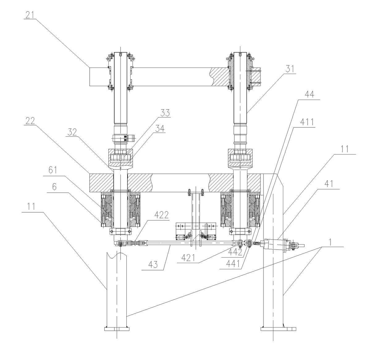
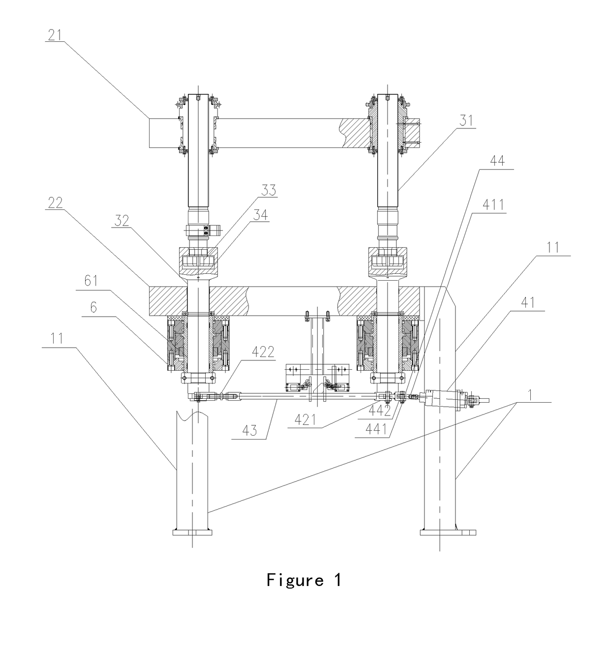
[0031]As shown in FIG. 1, the tire vulcanizing machine in the embodiment comprises a frame 1, a cross beam mechanism and a mold mechanism 7, the frame 1 comprises a plurality of supporting pillars 11, the quantity of the supporting pillar should be changed according to the specific structure, for example, two supporting pillars 11 should be arranged to support the parts if there are two pulling rods. The cross beam mechanism comprises an upper cross beam 21 and a lower cross beam 22. The lower cross beam 22 is connected with the frame 1. More particularly the lower cross beam 22 is horizontally connected with the supporting pillars 11 of the frame 1 between them. The upper cross beam 21 is in guiding connection with the lower cross beam 22 through a mold opening and closing guiding system (not shown in the figure). The mold mechanism is arranged between the upper cross beam 21 and the lower cross beam 22 with the upper end and the lower end of the mold mechanism being fixedly connec...


PUM

PropertyMeasurementUnit
structureaaaaaaaaaa
mold locking forceaaaaaaaaaa
driving forceaaaaaaaaaa

Abstract

A hydraulic tire vulcanizing machine includes a frame, a cross beam mechanism, a plurality of groups of pulling rods and a mold locking mechanism, and hydraulic oil cylinders. Each pulling rod includes an upper pulling rod unit and a disconnectable lower pulling rod unit. The upper pulling rod unit is fixedly connected to the upper cross beam, and the lower pulling rod unit is equipped through the lower cross beam and the corresponding hydraulic oil cylinder with the mold locking mechanisms being connected to the lower pulling rod units. Each mold locking mechanism includes a driving device, a swing link, a plurality of connectors and at least one ball pin boss in mutual connection. Detection devices are provided for upper and lower pulling rod units connecting position with each of the detection devices include an impactor and a limit switch. The impactor is arranged on the upper pulling rod unit.

Description

CROSS-REFERENCE TO RELATED APPLICATIONS[0001]This application is a Continuation of PCT International Application No. PCT / CN2013 / 070892, filed on Jan. 23, 2013, which claims priority under 35 U.S.C. 119(a) to Patent Application No. 201210582029.6, filed in China on Dec. 28, 2012, all of which are hereby expressly incorporated by reference into the present application.BACKGROUND OF THE INVENTION[0002]1. Field of the Invention[0003]The invention relates to a tire vulcanizing machine. More particularly to a hydraulic tire vulcanizing machine capable of realizing self-adaptive mold adjustment without a supporting plate.[0004]2. Description of Background Art[0005]A hydraulic tire vulcanizing machine is an important and main apparatus used in tire vulcanizing production having a much better accuracy than the traditional mechanical vulcanizing machine. Thus, the hydraulic tire vulcanizing machine is widely applied to the modern production of the tire vulcanization.[0006]The structure of the...

Claims


Application Information

Patent Timeline
Patent Type & Authority Patents(United States)
IPC IPC(8): B29C33/24B29C35/02B29D30/06B29L30/00
CPCB29C33/24B29D30/0601B29L2030/00
Inventor ZHANG, ZHENGLUO
Owner SINOARP TECH (SUZHOU) CO LTD
Why Eureka
Try Eureka