Liquid ejecting head and liquid ejecting apparatus

a liquid ejecting head and liquid ejecting technology, applied in the direction of printing, inking apparatus, etc., can solve the problems of insufficient adhesive strength or positional error of the wiring board, non-uniform characteristics, and failure to adhere or the lik

Active Publication Date: 2017-12-12
SEIKO EPSON CORP
View PDF6 Cites 3 Cited by
  • Summary
  • Abstract
  • Description
  • Claims
  • Application Information

AI Technical Summary

Benefits of technology

[0009]According to an aspect of the invention, there is provided a liquid ejecting head including: a plurality of driving elements which cause liquid to be ejected from nozzles by imparting pressure to a pressure chamber in which the liquid is filled, the plurality of driving elements including a plurality of first driving elements which are arranged along a first direction and a plurality of second driving electrodes which are arranged along the first direction at the opposite side to the plurality of first driving elements with a mounting region, in which a mounting component is installed, interposed therebetween; and a plurality of electrodes which are formed in the mounting region so as to extend along the second direction which intersects with the first direction, in which the plurality of electrodes include: a plurality of first electrodes which are arranged along the first direction in a first region within the mounting region and are electrically connected to the plurality of first driving elements; a plurality of second electrodes which are arranged along the first direction across the first region within the mounting region and a second region within the mounting region which is positioned at one side in the first direction viewed from the first region, and are electrically connected to the plurality of second driving elements; and a third electrode which does not contribute to ejection of the liquid and is formed between each of the second electrodes that are adjacent to one another along the first direction in the second region. In the above aspect, in the configuration where the first electrodes and the second electrodes are formed in the first region and the second electrodes are formed in the second region of the mounting region, the third electrodes that do not contribute to ejection of liquid are formed between each of the second electrodes which are adjacent to one another along the first direction within the second region. Accordingly, in comparison to the configuration where the third electrodes are not formed in the second region, the difference in density of the electrodes between the first region and the second region is reduced. That is, it is possible to uniformize density of the electrodes within the mounting region. According to a configuration where the numerical values of a pitch where the first electrodes and the second electrodes are arranged within the first region and a pitch where the second electrodes and third electrodes are arranged in the second region are equal, the effect in which it is possible to uniformize the densities of the electrodes within the mounting region is particularly remarkable.
[0013]In a configuration where each of the plurality of driving elements includes a first driving electrode, a piezoelectric body which is formed on an upper surface of the first driving electrode in a process including heat treatment, and a second driving electrode which is formed on an upper surface of the piezoelectric body, the first electrode is electrically connected to the first driving electrode of the first driving element, and the second electrode is electrically connected to the first driving electrode of the second driving element, in a heat treatment process in which a piezoelectric body is formed, it is possible that biasing in heat distribution occurs according to the presence or absence of the first electrodes and that a problem such as film formation failure of the piezoelectric body is caused. Considering the circumstances above, the liquid ejecting head according to the aspect of the invention includes fourth electrodes that are formed on the same layer as the first driving electrodes at an opposite side to another end section that interposes one end section in an array of the plurality of first driving elements. In the above aspect, since the fourth electrodes are formed on the same layer as the first driving electrodes at the opposite side to the other end section that interposes the one end section in an array of the plurality of first driving elements, biasing in heat distribution between the region in which the first driving elements are arranged and another region is reduced. Accordingly, it is possible to eliminate the problem such as film formation failure of a piezoelectric body of each driving element. As a result of the above, an interval between the first driving electrode of the first driving element and the first driving electrode of the second driving element is particularly remarkable in a wide configuration in comparison to the range in which the fourth electrodes are distributed along the first direction.
[0015]In the aspect of the invention, a virtual line that links a nozzle corresponding to a first driving element which is positioned at an end section at one side in the first direction among the plurality of first driving elements and a nozzle corresponding to a second driving element which is positioned at an end section at one side in the first direction among the plurality of second driving elements is inclined at an angle within the range of 30° to 60° inclusive in the first direction (further preferably, within the range of 30° to 40° inclusive, or 50° to 60° inclusive). In the above aspect, since the virtual line and the first direction are inclined to one another, in comparison, for example, to a configuration where a plurality of nozzles are arranged in a direction perpendicular to the first direction, it is possible to increase the dot density (resolution) in the direction.

Problems solved by technology

However, it is possible for various problems caused by the densities of the electrodes within the mounting region to occur.
For example, the degree of flow of an adhesive differs according to the densities of the electrodes within the mounting region in the process of mounting components of wiring boards or the like using an adhesive within the mounting region, and it is possible for a problem resulting in adhesion failure or the like to occur.
Alternatively, for example, in a case where a liquid ejecting head is heated in the manufacturing process, it is possible that biasing in heat distribution within the mounting region occurs according to the densities of the electrodes within the mounting region and non-uniformity of characteristics of the components formed hereafter is caused.
Here, based on the configuration where a flexible wiring board on which a plurality of connection terminals, which are electrically connected to the plurality of first electrodes and plurality of second electrodes, are formed is set as an electric wiring (e.g. a mounting component) and fixed using an adhesive, in a case where the densities of the electrodes in the first region and the second region are different, it is possible that the optimal coating amount and flow amount of the adhesive are different in the first region and the second region, therefore it is possible that a problem such as insufficient adhesive strength or positional error of the wiring board manifests.
In particular, in a configuration provided with a structure that includes a first wall surface positioned between the mounting region and a plurality of first driving elements and a second wall surface positioned between the mounting region and the second driving elements, it is possible for an error to occur at a position on the wiring board due to stress from the adhesive resulting from an excess of adhesive blocking the first wall surface and the second wall surface.

Method used


Image

  • Liquid ejecting head and liquid ejecting apparatus
  • Liquid ejecting head and liquid ejecting apparatus
  • Liquid ejecting head and liquid ejecting apparatus

Examples


first embodiment

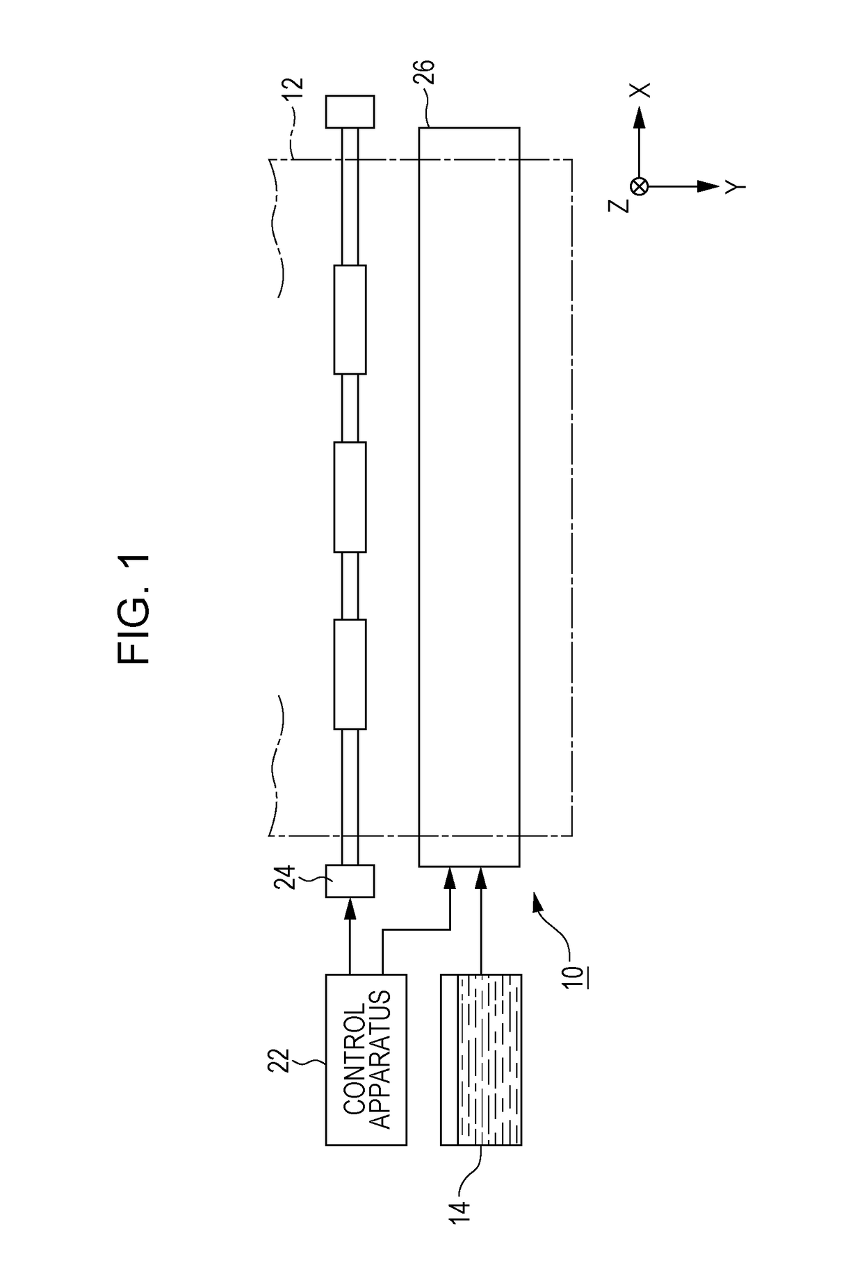
[0030]FIG. 1 is a partial configuration diagram of an ink jet type printing apparatus 10 according to a first embodiment of the invention. The printing apparatus 10 of the first embodiment is a liquid ejecting apparatus which ejects ink, which is an exemplification of a liquid, onto a medium 12 (ejection target) such as printing paper and includes a control device 22, a transport mechanism 24, and a liquid ejecting module 26. A liquid container (cartridge) 14 which retains ink of a plurality of colors is mounted in the printing apparatus 10. In the first embodiment, ink of four colors: cyan (C); magenta (M); yellow (Y); and black (B) is retained in the liquid container 14.

[0031]The control device 22 collectively controls each of the components of the printing apparatus 10. The transport mechanism 24 transports the medium 12 in the Y direction under control by the control device 22. The liquid ejecting module 26 ejects ink supplied from the liquid container 14 onto the medium 12 unde...

second embodiment

[0060]The second embodiment of the invention will be described below. Here, in each of the aspects exemplified below, concerning components which have the same actions and functions as the first embodiment, detailed explanation will be omitted as appropriate by using the same reference numerals which are explained in the first embodiment.

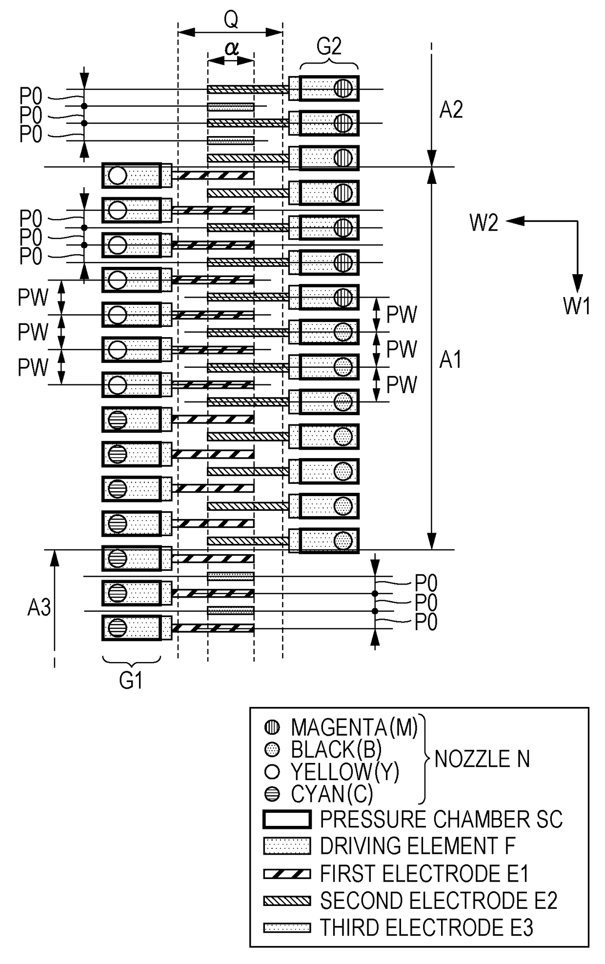
[0061]FIG. 8 is a schematic diagram of each component viewed from the negative side in the Z direction of the liquid ejecting head 30 according to a second embodiment. As exemplified in FIG. 8, the liquid ejecting head 30 of the second embodiment includes a plurality of dummy elements FD which are not actually utilized in ejection of ink. In detail, as exemplified in FIG. 8, the plurality of dummy elements FD are formed between the plurality of driving elements F which correspond to yellow and the plurality of driving elements F which correspond to cyan out of the first nozzle row G1 (that is, between colors of the first nozzle row N1) and the plura...

third embodiment

[0068]FIG. 9 is a schematic diagram of each component viewed from the negative side in the Z direction of the liquid ejecting head 30 according to a third embodiment. As exemplified in FIG. 9, in the third embodiment, a plurality of pressure chambers SD are formed at the positive side and the negative side in the W1 direction viewed from the pressure chambers SC which correspond to each of the driving elements F of the first element group G1. In the same manner, a plurality of the pressure chambers SD are formed at the positive side and the negative side in the W1 direction viewed from the pressure chambers SC which correspond to each of the driving elements F of the second element group G2. In the same manner to the second embodiment, each pressure chamber SD is formed with a structure in the same manner as the pressure chamber SC and is a pseudo-space which is not actually utilized in ejection of ink.

[0069]In the configuration where the pressure chambers SD are not formed at both ...


PUM


Abstract

A liquid ejecting head includes driving elements and electrodes each extending a second direction for ejecting liquid of pressure chambers through nozzles. The driving elements are classified into a first element group and a second element group. The electrodes are arranged along a first direction intersecting the second direction and are classified into a first electrode group electrically connected to the first element group, a second electrode group electrically connected to the second element group and a third electrode group not contribute to the ejecting liquid.

Description

CROSS-REFERENCE TO RELATED APPLICATIONS[0001]This application claims priority to Japanese Patent Application No. 2014-159063 filed on Aug. 4, 2014 and Japanese Patent Application No. 2014-159064 filed on Aug. 4, 2014. The entire disclosures of Japanese Patent Application Nos. 2014-159063 and 2014-159064 are hereby incorporated herein by reference.BACKGROUND[0002]1. Technical Field[0003]The present invention relates to a technique for ejecting liquid such as ink.[0004]2. Related Art[0005]Various techniques for ejecting liquid such as ink onto a medium such as printing paper are proposed in the related art. For example, JP-A-2013-103429 discloses a liquid ejecting head which causes ink inside a pressure chamber to be ejected from a nozzle by driving each of a plurality of piezoelectric elements that are arranged in two rows of a first row and a second row. A plurality of electrodes (connection terminals) for electrically connecting the plurality of piezoelectric elements to wirings on...

Claims


Application Information

Patent Timeline
Patent Type & Authority Patents(United States)
IPC IPC(8): B41J2/14B41J2/21
CPCB41J2/14B41J2/14233B41J2/2146B41J2202/20B41J2002/14419B41J2002/14491B41J2002/14362
Inventor OKUI, HIROAKISHIMOSAKA, TAKAYUKISATO, NAOYATAKAAI, HITOSHI
Owner SEIKO EPSON CORP
Why Eureka
Try Eureka