Photoelectric sensor

a technology of photoelectric sensor and display section, which is applied in the direction of 2d-image generation, editing/combining figures or text, instruments, etc., can solve the problems of limited display section size of photoelectric sensor and influence of display form of display section on the degree of user operability, so as to enhance display flexibility of display section and improve user operability

Active Publication Date: 2017-12-12
KEYENCE
View PDF34 Cites 5 Cited by
  • Summary
  • Abstract
  • Description
  • Claims
  • Application Information

AI Technical Summary

Benefits of technology

[0018]An object of the present invention is to provide a photoelectric sensor capable of enhancing display flexibility of a display section mounted on the photoelectric sensor, and making this display flexibility contribute to improvement in user's operability.
[0019]In order to achieve the above technical object, a first characteristic of a photoelectric sensor of the present invention lies in adoption of a dot-matrix display as a display section. A typical example thereof is a liquid crystal display. By adopting the dot-matrix display, it is possible to acquire display flexibility which is incomparably higher than that of a seven-segment LED.

Problems solved by technology

However, a size of the display section of the photoelectric sensor is limited, and on the other hand, there are various types of information to be displayed due to multi-functionalization of the photoelectric sensor.
In the photoelectric sensor that can only adopt a display with a limited display area, even when the dot-matrix display is adopted and the flexibility of a display form instantly increases, it adversely causes the display form of the display section to have an influence on the degree of the user's operability.
Further, when some abnormality occurs, if the dot-matrix display is in use, this abnormal state can be displayed in characters such as letters.

Method used


Image

  • Photoelectric sensor
  • Photoelectric sensor
  • Photoelectric sensor

Examples


embodiment

[0108]FIG. 24 is a plan view of a photoelectric sensor 300 of the embodiment. This photoelectric sensor 300 is a distance setting photoelectric sensor, and a box-type photoelectric sensor. Although the photoelectric sensor of JP 2007-33097 A is the slim-type photoelectric sensor, since an internal configuration of the photoelectric sensor 300 is substantially the same as that of the photoelectric sensor of JP 2007-33097 A, a detailed description thereof is omitted as the disclosure of JP 2007-33097 A is cited in the present specification.

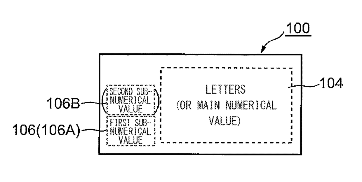
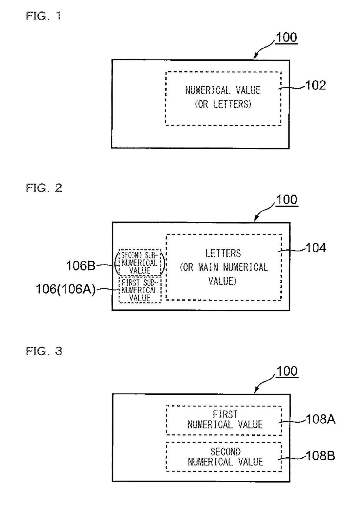
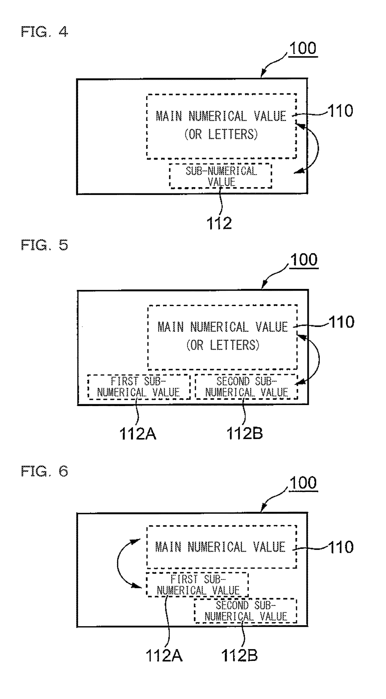
[0109]Referring to FIG. 24, a top surface 300a, namely, an operation surface, of the photoelectric sensor 300 is provided with the rectangular display section 100 described with reference to FIGS. 1 to 7, and provided with the first to third button switches 120A to 120C described with reference to FIGS. 8 to 11. The first button switch 120A adjacent to the left end of the display section 100 is referred to as a “SET switch” or a “SET button” in this...


PUM


Abstract

Provided is a photoelectric sensor capable of enhancing display flexibility of a display section mounted on the photoelectric sensor and making this display flexibility contribute to improvement in user's operability. In a Run mode, a current value is displayed in large-sized numerals on a display section. When switching is made from the Run mode to a setting mode and letter information is to be displayed in the setting mode, a current value is displayed in relatively small-sized numerals at the corner (e.g., lower left) of the display section.

Description

CROSS-REFERENCE TO RELATED APPLICATIONS[0001]The present application claims foreign priority based on Japanese Patent Application No. 2013-220614, filed Oct. 23, 2013, the contents of which is incorporated herein by reference.BACKGROUND OF THE INVENTION[0002]1. Field of the Invention[0003]The present invention relates to a photoelectric sensor provided with a display part.[0004]2. Description of Related Art[0005]There are the following types of photoelectric sensors: a first-type photoelectric sensor that detects presence or absence of an object to be detected (hereinafter, referred to as “workpiece”) based on a light reception amount of received light; and a second-type photoelectric sensor that detects the presence or absence of a workpiece mainly based on a distance to the workpiece. The second-type photoelectric sensor is called a “distance setting photoelectric sensor”. JP 2005-210720 A (JP 4023621 B2) and U.S. Pat. No. 6,555,806 disclose the first-type photoelectric sensor. JP...

Claims


Application Information

Patent Timeline
Patent Type & Authority Patents(United States)
IPC IPC(8): G06T11/00G06F3/01G01B11/14G01D7/00G06T11/60
CPCG06F3/01G06T11/60G01D7/00G01B11/14G06F3/04812G06F3/04847
Inventor HANADA, TOMOKI
Owner KEYENCE
Why Eureka
Try Eureka