Hinge assembly and foldable display device using the same

a display device and hinge assembly technology, applied in the field of hinge assembly and foldable display devices, can solve the problems of uneven image display, poor use experience, and shorten the life of flexible display members

Active Publication Date: 2017-12-19
SHIN ZU SHING
View PDF22 Cites 94 Cited by
  • Summary
  • Abstract
  • Description
  • Claims
  • Application Information

AI Technical Summary

Benefits of technology

[0008]Concisely, according to embodiments of the present invention of a hinge assembly and a foldable display device using the hinge assembly, when the foldable display device is being spread, the first plate member and the second plate member is moving away from each other along with the increase of a spreading angle. When the foldable display device is completely spread and is in a spreading state, the first side and the second side are spaced by a predetermined distance. The predetermined distance is corresponding to a middle portion of a flexible display member, which allows the flexible display member to form an even, flat surface. As a result, the issue of the prior art that a middle portion of a foldable display device humps when the foldable display device is spread can be solved.

Problems solved by technology

As a result, the experience of use is bad, the image displaying is uneven, and the lifespan of the flexible display member is shortened.
These hinges can be applied to portable devices; however, these hinges cannot be applied to flexible displays.
The issue that a middle portion between two plate members (i.e., a base and a cover) of the flexible display humps when the two plate members are spread to form a surface is still not solved.
2015 / 0362958 and 2015 / 0267450; however, it does not solve the issue of humping of the flexible display.

Method used


Image

  • Hinge assembly and foldable display device using the same
  • Hinge assembly and foldable display device using the same
  • Hinge assembly and foldable display device using the same

Examples


Embodiment Construction

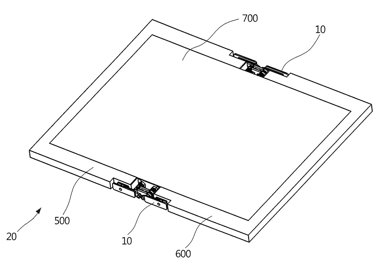
[0018]Please refer to FIGS. 2, 3, and 3A. FIG. 2 illustrates a perspective view of a foldable display device 20 according to an embodiment of the present invention. FIG. 3 illustrates an exploded view of the foldable display device 20 according to an embodiment of the present invention. FIG. 3A illustrates an enlarged view of a hinge assembly 10 of FIG. 3. The foldable display device 20 comprises a first plate member 500, a second plate member 600, a hinge assembly 10, and a flexible display member 700. For example, the flexible display member 700 may be, but not limited to, a flexible organic light emitting diode (OLED) panel. As shown in FIG. 3, the first plate member 500 comprises a first display surface 510 and a first side 520 at a side of the first display surface 510. The second plate member 600 comprises a second display surface 610 and a second side 620 at a side of the second display surface 610. The first side 520 and the second side 620 are close to each other.

[0019]Plea...


PUM


Abstract

A foldable display device includes a first plate member, a second plate member, a hinge assembly, and a flexible display member. The first plate member includes a first display surface and a first side. The second plate member includes a second display surface and a second side. The first side and the second side are close to each other. A first hinge member and a second hinge member of the hinge assembly are respectively connected to the first plate member and the second plate member. The flexible display member includes a first portion, a second portion, and a middle portion. The first portion contacts the first display surface. The second portion contacts the second display surface. The middle portion is between the first side and the second side. The first and second hinge members rotate relatively to have the flexible display member spread to be flat.

Description

FIELD OF THE INVENTION[0001]The present invention relates to a display device and, more particularly, to a hinge assembly and a foldable display device using the same.BACKGROUND OF THE INVENTION[0002]Please refer to FIG. 1. FIG. 1 illustrates a perspective view of a foldable display device 20a according to prior art. The conventional foldable display device 20a comprises a first plate member 500a and a second plate member 600a pivotally connected to each other and capable of being folded and spread. A flexible display member 700a is disposed on a front face of the first plate member 500a and the second plate member 600a. When the first plate member 500a and the second plate member 600a are folded relatively, the flexible display member 700a completely attaches to a front face 501 of the first plate member 500a and a front face 601 of the second plate member 600a, and a middle portion 730a of the flexible display member 700a attaches to a side 502 of the first plate member 500a and a...

Claims


Application Information

Patent Timeline
Patent Type & Authority Patents(United States)
IPC IPC(8): G06F1/16H05K7/00H05K5/00H05K5/02E05D7/00F16C11/04E05D3/14
CPCH05K5/0226F16C11/04E05D3/14E05D7/00H05K5/0017E05Y2900/606H04N5/64E05Y2800/102E05D3/122E05D3/18E05D11/1078G06F1/1681
Inventor CHU, JUI-LINHSU, KUO-JUNG
Owner SHIN ZU SHING
Why Eureka
Try Eureka