Locking device for rocker switch

Active Publication Date: 2018-01-02
MARTINEZ CARLOS M
View PDF23 Cites 5 Cited by
  • Summary
  • Abstract
  • Description
  • Claims
  • Application Information

AI Technical Summary

Benefits of technology

[0030]In view of the foregoing an object of the present invention is to provide a locking devi

Problems solved by technology

The rocker switch when used in a conventional manner may be accidentally depressed to turn on a light, activate an alarm or even injure someone working on the electrical system.
In most cases, there are no labels placed on the individual switches so that it may be difficult to know if the device is on or off.
Inadvertent activation of the switch to its “on” position while work is being

Method used


Image

  • Locking device for rocker switch
  • Locking device for rocker switch
  • Locking device for rocker switch

Examples


Embodiment Construction

[0067]A detailed description of one or more embodiments is provided below along with accompanying Figures that illustrate the principles of the embodiments. The scope of the embodiments is limited only by the claims and encompasses numerous alternatives, modifications and equivalents. Numerous specific details are set forth in the following description. These details are provided solely for the purposes of example and the embodiments may be practiced according to the claims without some or all of these specific details.

[0068]Referring now to the drawings, in which like numerals represent like elements throughout the several views.

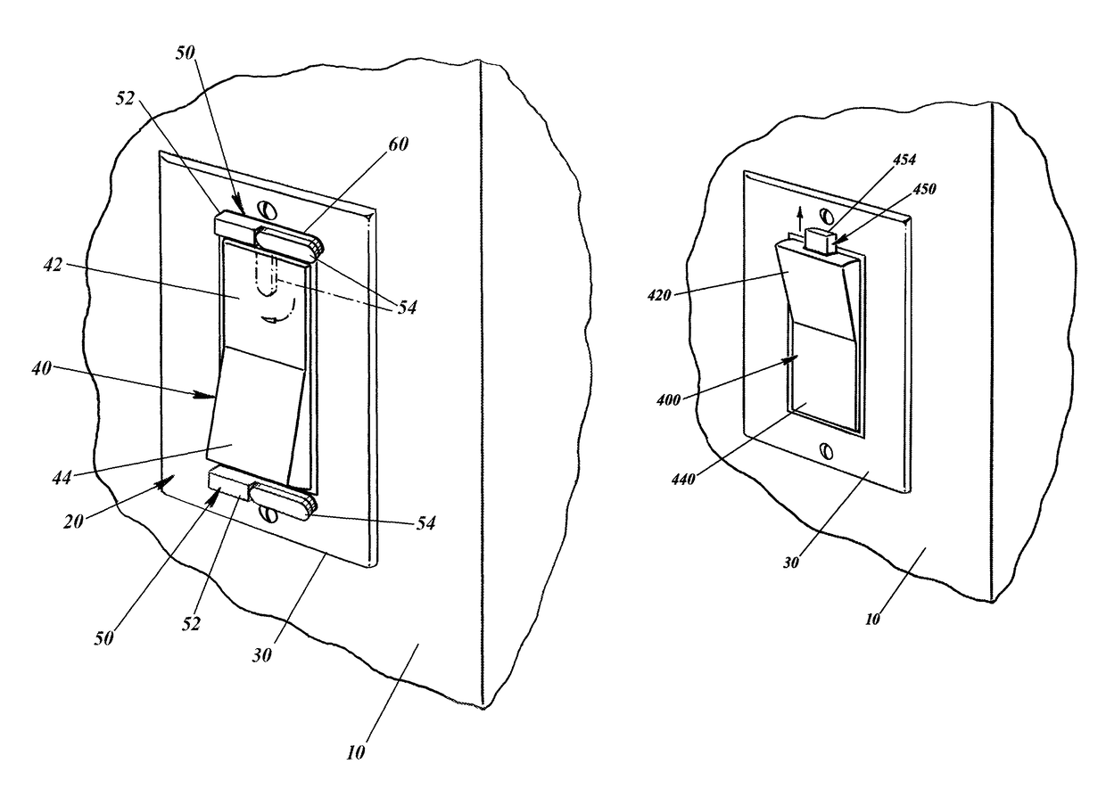
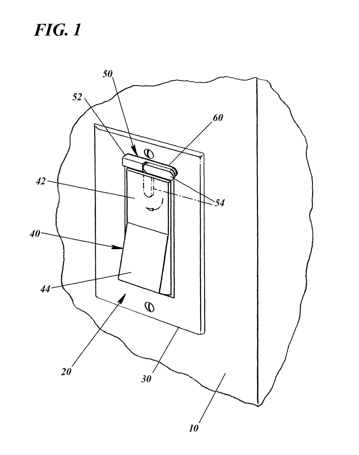
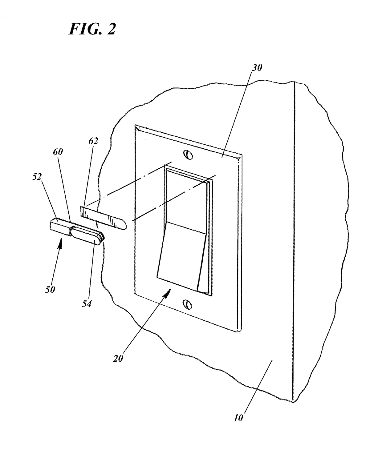
[0069]FIGS. 1 through 6 illustrate a first embodiment of the locking device 50 of this invention installed on an existing rocker switch 40. It should be noted that although a standard vertical rocker wall switch 40 is shown, the same type of locking device 50 could be adapted for usage with other types of rocker switches such as horizontally disposed rocker...


PUM


Abstract

A locking device for a rocker switch that has an elongated member having a top edge, a bottom edge, opposite ends, a front facing surface and a rear facing surface. A toggle member is pivotally mounted to the front facing surface. The toggle member pivots between a first toggle position that extends below the bottom edge of the elongated member and a second toggle position that does not extend below the bottom edge. The rear facing surface of the elongated member is mounted to the switch plate cover, the bottom edge of the elongated member adjacent the first end of the rocker switch. When the first end of the rocker switch is pivoted to the first position the toggle may be pivoted to the first toggle position to extend below the lower edge of the elongated member to overlie the first end of the rocker switch to lock the rocker switch in the first position. The toggle may be pivoted to the second toggle position to unlock the rocker switch from the first position. A locking device may be provided for each end of the rocker switch. Locking devices built into the ends of the rocker switch are also described.

Description

FIELD OF THE INVENTION[0001]This invention relates to a rocker switches of the type which are typically wall-mounted and are used to turn on and off for example, electric lights. In particular, this invention relates to a safety device either added as an accessory or built into a rocker switch to prevent the erroneous switching of the rocker switch from one position, e.g., “on” to a second position, e.g., “off”.BACKGROUND OF THE INVENTION[0002]Electrical circuits in residential and commercial buildings are often controlled by rocker switches. A rocker switch is typically surrounded by a switch plate cover. The rocker switch has opposite ends that are pivotable about a pivot axis between the ends. The rocker switch is movable between a first position, e.g., “on” wherein the first end is substantially flush with a first portion of the switch plate and a second position, e.g., “off” wherein the second end is substantially flush with a second portion of the switch plate. The rocker swit...

Claims


Application Information

Patent Timeline
IPC IPC(8): H01H9/28H01H23/04H01H3/20
CPCH01H9/282H01H3/20H01H23/04H01H9/283H01H9/28H01H9/286H01H23/145
Inventor MARTINEZ, CARLOS M.
Owner MARTINEZ CARLOS M
Why Eureka
Try Eureka