Waterproof connector

a technology of waterproof connectors and connectors, applied in the direction of coupling contact members, coupling device connections, connections effected by permanent deformation, etc., can solve the problem of reducing the sealability of waterproof packing for the wires arranged in the central part, and achieve the effect of preventing the enlargement of a waterproof connector and enhanced the sealability of each wir

Active Publication Date: 2018-01-02
SUMITOMO WIRING SYST LTD
View PDF11 Cites 6 Cited by
  • Summary
  • Abstract
  • Description
  • Claims
  • Application Information

AI Technical Summary

Benefits of technology

[0008]According to this configuration, by providing the recesses and the compressing protrusions behind the laterally long terminal accommodation areas where the terminal accommodating portions are formed, it is possible to press the seal in the directions to reduce the through holes in diameter at positions along the through holes while effectively utilizing dead spaces formed behind the terminal accommodating portions. In this way, it is possible to enhance sealability between each wire and the seal while preventing the enlargement of the rear holder, and consequently, of the waterproof connector.
[0009]The recesses may be formed over a range of the plurality of through holes. According to this configuration, a plurality of through holes can be reduced in diameter collectively by one compressing protrusion. Thus, the structures of the seal and the rear holder can be simplified and the production cost of the waterproof connector can be reduced.
[0011]According to the technique disclosed by this specification, it is possible to enhance sealability for each wire while preventing the enlargement of a waterproof connector.

Problems solved by technology

Further, if wire insertion holes are formed in plural stages and arranged in vertical and lateral directions, the insertion holes arranged in a central part cannot be compressed merely by compressing the waterproof packing from the outer side and the sealability of the waterproof packing for the wires arranged in the central part is reduced.

Method used


Image

  • Waterproof connector
  • Waterproof connector
  • Waterproof connector

Examples


first embodiment

[0028]A first embodiment is described with reference to FIGS. 1 to 12.

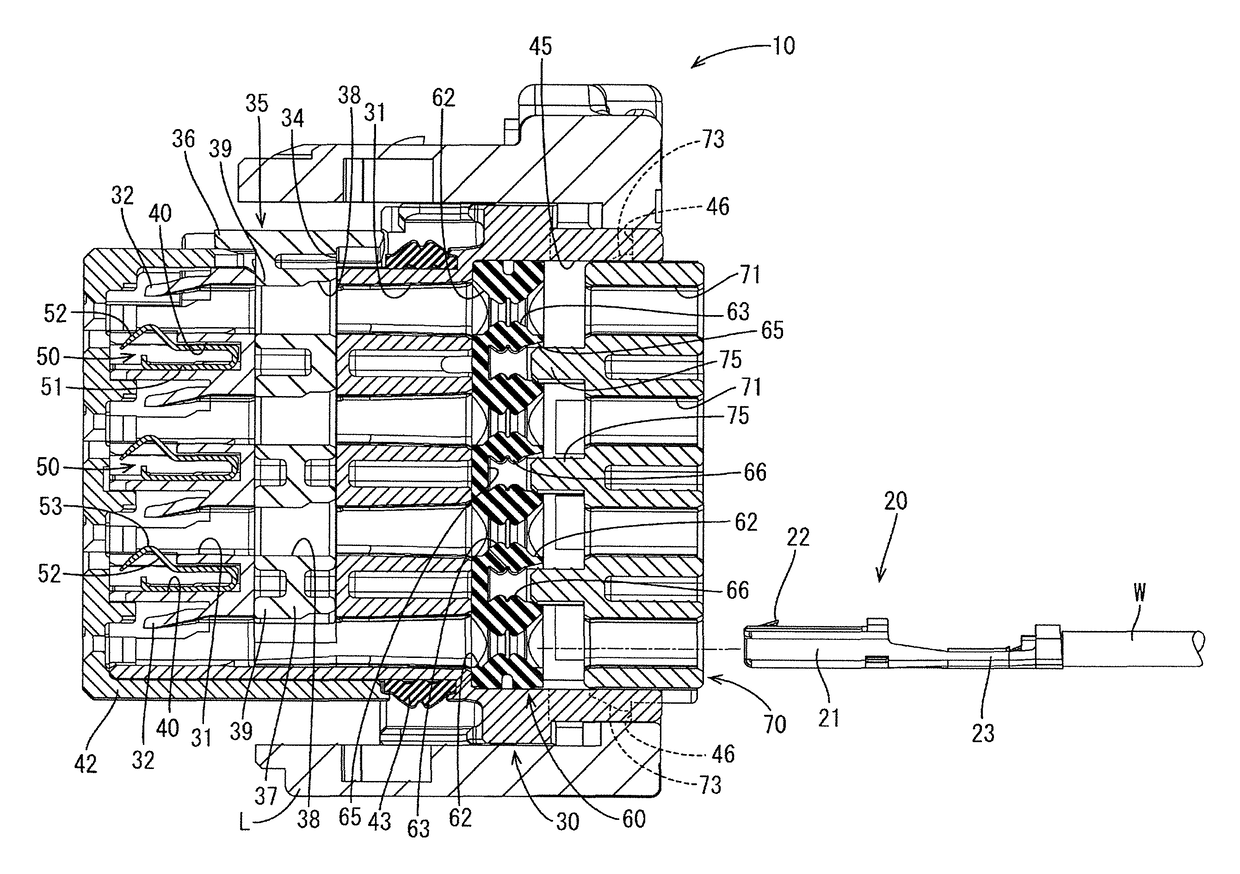
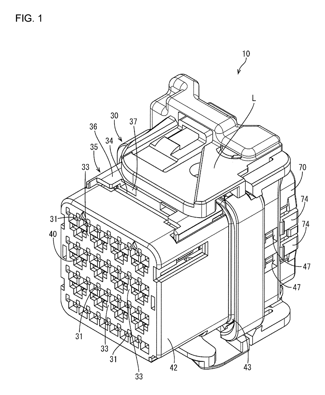
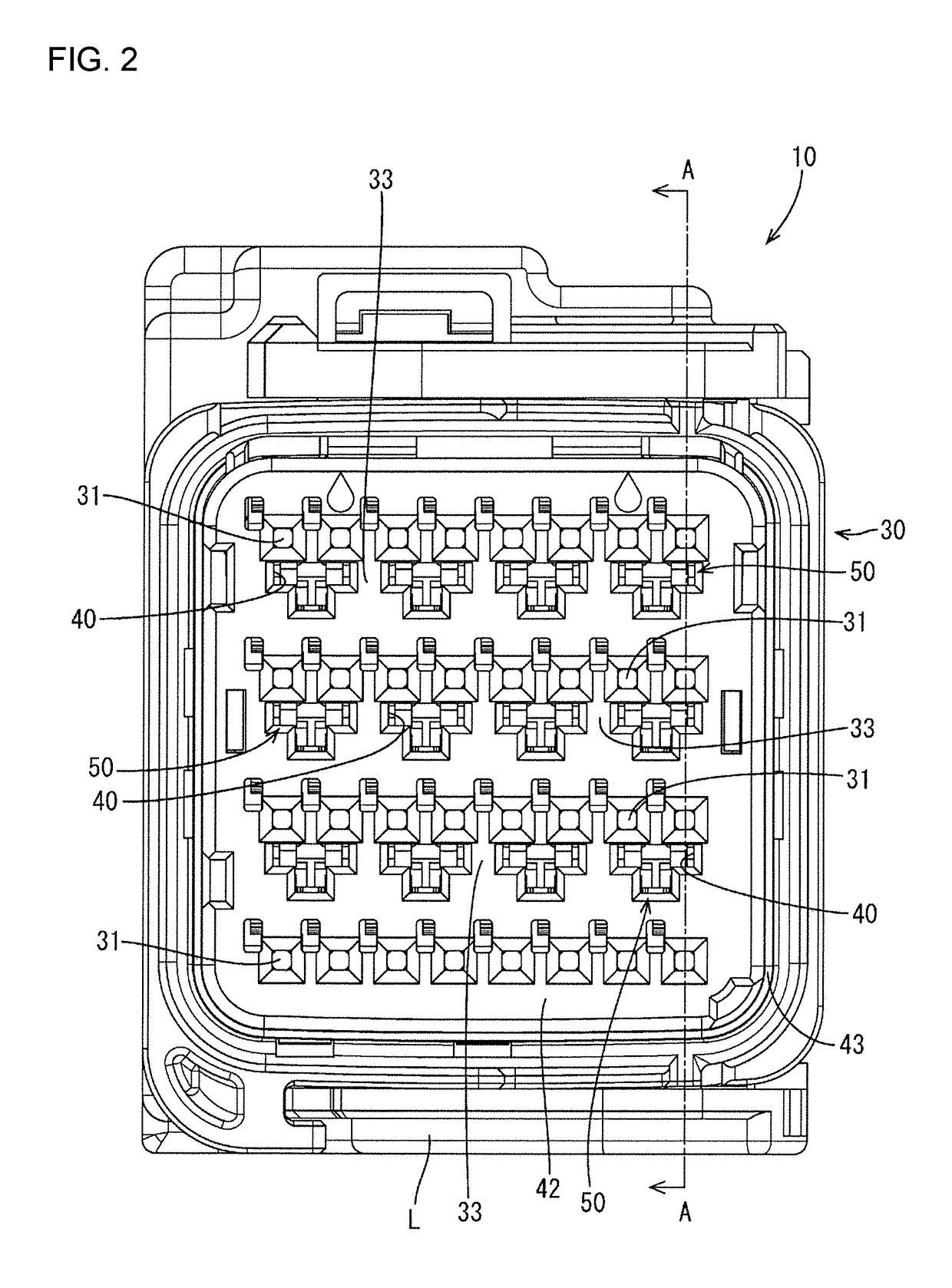
[0029]A waterproof connector 10 including a lever L for assisting the connection and separation to and from an unillustrated mating connector by being rotated is illustrated in this embodiment. As shown in FIGS. 10 to 12, the waterproof connector 10 includes female terminals (an example of “terminal fittings”) 20 to be connected to ends of wires W, a female housing (an example of a “housing”) 30 made of synthetic resin and formed with a plurality of cavities 31 arranged such that the female terminals 20 and the wires W are accommodated thereinto from behind, shorting terminals 50 for shorting a plurality of female terminals 20, a one-piece rubber plug (an example of a “seal”) 60 to be fitted into a rear part of the female housing 30 and a rear holder 70 made of synthetic resin and configured to prevent the one-piece rubber plug 60 from coming out backward by being mounted into a rear end part of the female housing...

second embodiment

[0067]Next, a second embodiment is described with reference to FIGS. 13 to 16.

[0068]A waterproof connector 110 of the second embodiment differs from the first embodiment in the number of the cavities 31 of the female housing 30, the number of the through holes 62 of the one-piece rubber plug 60, the width of the recesses 65, the number of insertion holes 71 of the rear holder 70 and the width of the compressing protrusions 75. Configurations, functions and effects common to the first embodiment are not described to avoid repeated description. Further, the same components as in the first embodiment are denoted by the same reference signs.

[0069]The number of cavities 31 in a female housing 130 of the second embodiment is larger by 1 than that of the cavities 31 of the female housing 30 in the first embodiment in the width direction as shown in FIG. 13 and, associated with this, the number of through holes 62 of a one-piece rubber plug 160 and that of insertion holes 71 of a rear holde...


PUM


Abstract

A waterproof connector (10) includes a female housing (30) formed with cavities (31), and female terminals (20) connected to ends of wires (W) are inserted into the cavities (31) from behind. Shorting terminals (50) are accommodated in terminal accommodating portions (40) in a front part of the housing (30) to short adjacent female terminals (20). A one-piece rubber plug (60) is fit into a rear part of the housing (30) and includes through holes (62) through which the wires (W) are to be inserted. A rear holder (70) is mounted into the housing (30) to retain the one-piece rubber plug (60). Recesses (65) are provided on the one-piece rubber plug (60) in areas behind the terminal accommodating portions (40). Compressing protrusions (75) project from the rear holder (70) and are press-fit into the recesses (65) from behind.

Description

BACKGROUND[0001]1. Field of the Invention[0002]The invention relates to a waterproof connector.[0003]2. Description of the Related Art[0004]Japanese Unexamined Patent Publication No. 2002-252056 discloses a waterproof connector including a waterproof packing formed with a plurality of wire insertion holes. The waterproof packing is fit into a rear part of a housing from behind and retained by a rear holder mounted on a rear end part of the housing. The rear holder is movable in a front-back direction between a partial locking position and a full locking position. The rear holder is provided with an annular portion surrounding the outer periphery of the waterproof packing. When the rear holder is moved from the partial locking position to the full locking position, the annular portion compresses the waterproof packing inwardly from an outer side, thereby enhancing a close contact force between the wires and the waterproof packing.[0005]According to the waterproof connector of Japanes...

Claims


Application Information

Patent Timeline
Patent Type & Authority Patents(United States)
IPC IPC(8): H01R13/52H01R4/18H01R13/11H01R13/436H01R13/506
CPCH01R13/5208H01R4/18H01R13/506H01R13/4367H01R13/11
Inventor HARA, TERUONAKANISHI, YUICHI
Owner SUMITOMO WIRING SYST LTD
Why Eureka
Try Eureka