Cardiac valve downsizing device and method

a heart valve and valve downsizing technology, applied in the field of heart valve repair and/or replacement techniques, annuloplasty devices, can solve the problems of valve support non-functionality, valve leakage, valve insufficiency, etc., and achieve the effect of simplifying the rest of the valve repair or replacement procedure and reducing complexity and tim

Active Publication Date: 2018-01-16
MEDTENTIA INT LTD OY
View PDF5 Cites 18 Cited by
  • Summary
  • Abstract
  • Description
  • Claims
  • Application Information

AI Technical Summary

Benefits of technology

[0018]In comparison with conventional annuloplasty, with the Parachute procedure, where the downsizing of a dilated valve and the reshaping as well as the fixation of the support ring are highly integrated into a tedious process, embodiments of the present invention provide for a separation (in time) of downsizing and reshaping. In particular, embodiments of the present invention provide for an advantageous downsizing, substantially simplifying the remainder of the valve repair or replacement procedure.
[0019]Embodiments, thus provide for both reducing complexity and time of previously known procedures.

Problems solved by technology

The mitral and tricuspid valve leaflets or supporting chordae may degenerate and weaken or the annulus may dilate leading to valve leak (valve insufficiency).
The leaflets and chordae may become calcified and thickened rendering them stenotic (obstructing forward flow).
If the ventricle changes in shape, the valve support may become non-functional and the valve may leak.
This simultaneous downsizing of the valve annulus and, which is time consuming and tedious.
A result of such a procedure may differ greatly and even provide a non-desired result, very much depending on the skills of the surgeon performing the procedure.
However, the disclosure of US2007 / 0038293 does only provide local modification of certain portions of a heart valve, e.g. by grasping one or more leaflets for bringing these into a position suitable for fixation of a clip to the leaflets.
However, the devices are not providing an active downsizing.

Method used


Image

  • Cardiac valve downsizing device and method
  • Cardiac valve downsizing device and method
  • Cardiac valve downsizing device and method

Examples


Embodiment Construction

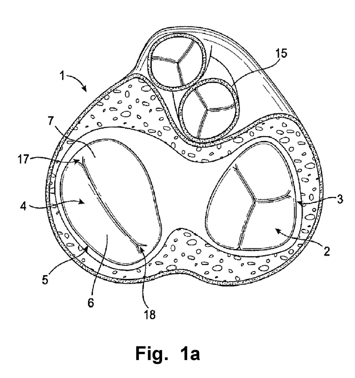
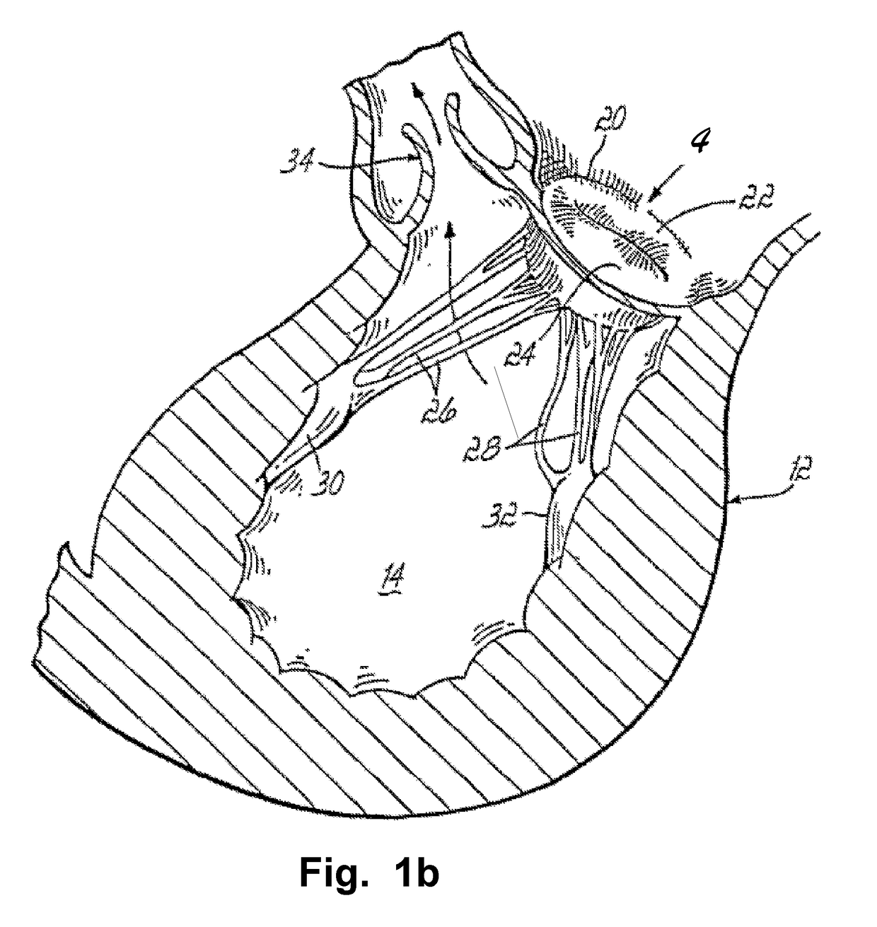
[0054]Specific embodiments of the invention will now be described with reference to the accompanying drawings. This invention may, however, be embodied in many different forms and should not be construed as limited to the embodiments set forth herein; rather, these embodiments are provided so that this disclosure will be thorough and complete, and will fully convey the scope of the invention to those skilled in the art. The terminology used in the detailed description of the embodiments illustrated in the accompanying drawings is not intended to be limiting of the invention. In the drawings, like numbers refer to like elements.

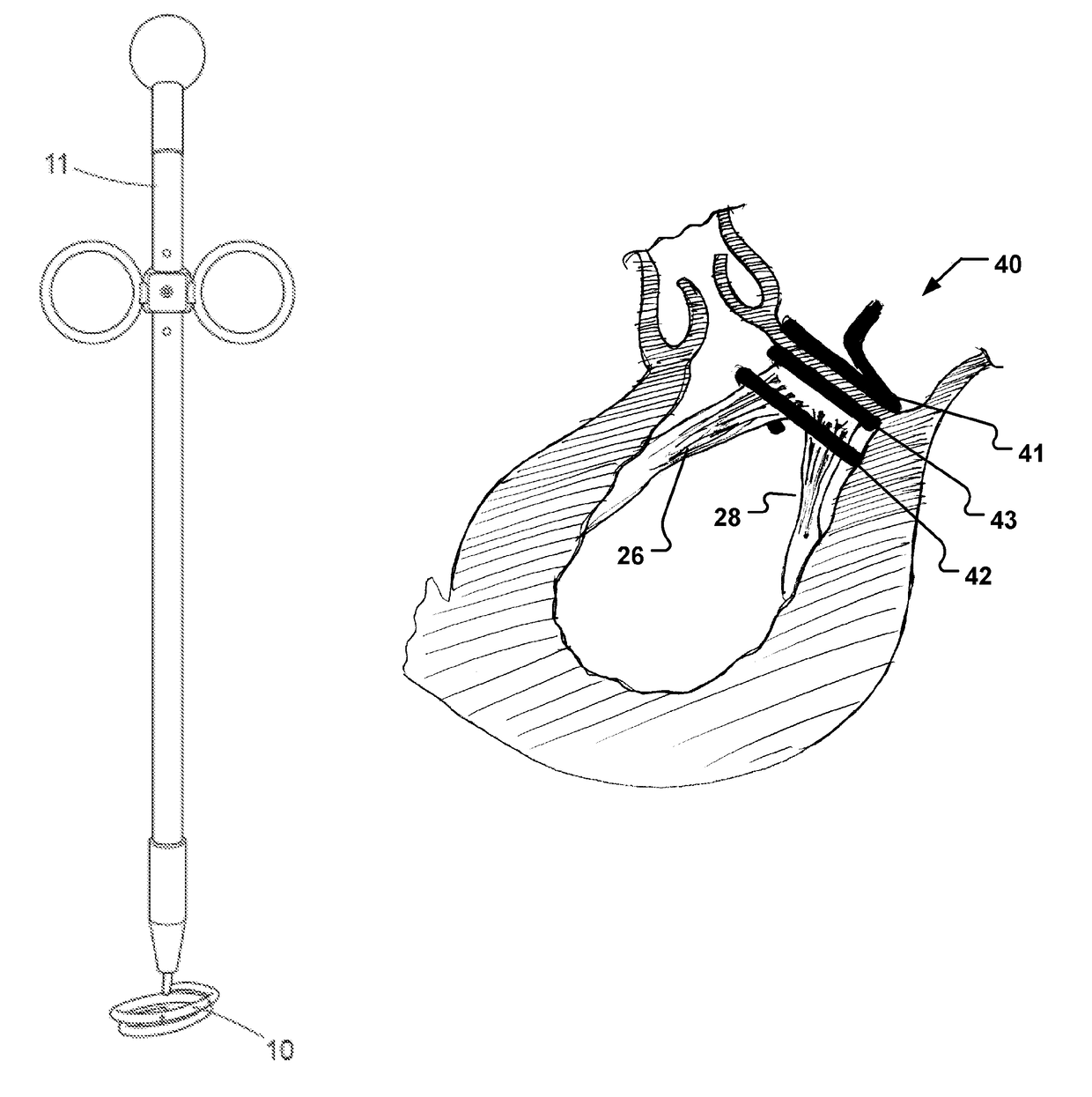
[0055]The following description focuses on an embodiment of the present invention applicable to a repair of a defective heart valve and in particular to a reshaping the valve shape and / or area in order to facilitate insertion of an annuloplasty implant and / or artificial heart valve. However, it will be appreciated that the invention is not limited to this appl...


PUM


Abstract

A device for repairing a heart valve comprises a medical device (10). The medical device (10) comprises an element in order to downsize the annulus upon insertion and allow the leaflets to open and close properly. The medical device (10) provides a temporary or permanent downsizing of the heart valve. An annuloplasty implant and / or heart valve prosthesis is in embodiments releasably attached to the medical device for insertion to the annulus and permanent fixation of the latter in a desired shape.

Description

RELATED APPLICATIONS[0001]The present invention claims priority to International Patent Application No. PCT / EP2008 / 068126, International Filing date Dec. 20, 2008, entitled Cardiac Valve Downsizing Device And Method, which claims benefit of European Patent Application No. EP07124048.5 filed Dec. 12, 2007 entitled Pre-Annuloplasty Device and Method, and U.S. Provisional Application Ser. No. 61 / 016,331, filed Dec. 21, 2007 entitled Pre-Annuloplasty Device and Method; all of which are incorporated herein by reference in their entireties.FIELD OF THE INVENTION[0002]The present invention generally relates to heart valve repair and / or replacement techniques, annuloplasty devices, and related tools. More specifically, the invention relates to a medical device devised for facilitating or providing such heart valve repair techniques and / or heart valve replacement techniques for the repair of defective heart valves.BACKGROUND OF THE INVENTION[0003]Diseased mitral and tricuspid valves frequent...

Claims


Application Information

Patent Timeline
Patent Type & Authority Patents(United States)
IPC IPC(8): A61F2/24
CPCA61F2/2445A61F2/2466A61F2250/006A61F2/2457A61F2230/0091A61F2/2448A61F2/2409A61B17/12A61M25/01
Inventor KERANEN, OLLIANTONSSON, PER
Owner MEDTENTIA INT LTD OY
Why Eureka
Try Eureka