Method for determining active input elements of an input arrangement and input arrangement

a technology of active input elements and input arrangement, applied in the field of input arrangement, can solve the problems of simple construction keyboards having detection problems, still some problems, etc., and achieve the effect of reducing the length of the plateau, easy control, and more precise control

Active Publication Date: 2018-01-23
HELDEIS CHRISTOPH
View PDF10 Cites 6 Cited by
  • Summary
  • Abstract
  • Description
  • Claims
  • Application Information

AI Technical Summary

Benefits of technology

[0007]It is an object of the invention to provide a method that may be used in a simple manner and that preferably deals with the problems of wrong key switch detection and / or of multiple key switch detection of key switches that are pressed at the same time. Preferably it shall be easy and / or fast to determine which key switches is / are pressed. Furthermore, a corresponding input arrangement should be provided.
[0379]The technical effect is a reduction of the number of reports and / or endpoints. At least the first endpoint may be used if the main operating system cannot deal with larger reports.

Problems solved by technology

However, there are still some problems.
Simply constructed keyboards often have problems with the detection if multiple key switches are activated at the same time.

Method used


Image

  • Method for determining active input elements of an input arrangement and input arrangement
  • Method for determining active input elements of an input arrangement and input arrangement
  • Method for determining active input elements of an input arrangement and input arrangement

Examples


Embodiment Construction

—ASPECT A

[0419]The making and using of the presently preferred embodiments are discussed in detail below. It should be appreciated, however, that the present invention provides many applicable inventive concepts that can be embodied in a wide variety of specific contexts. The specific embodiments discussed are merely illustrative of specific ways to make and use the invention, and do not limit the scope of the invention. Moreover, the same reference signs refer to the same technical features if not stated otherwise. As far as “may” is used in this application it means the possibility of doing so as well as the actual technical implementation.

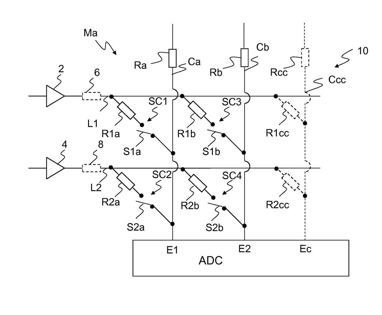
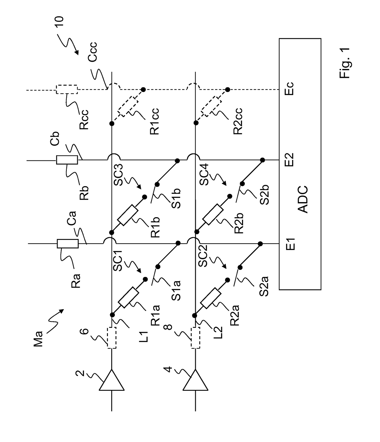
[0420]FIG. 1 illustrates a matrix of an input arrangement 10, for instance of a keyboard. The input arrangement 10 comprises a matrix M of conductive lines Ca, Cb that form the columns and of conductive lines L1, L2 that form the rows of the matrix M. The conductive lines L1, L2 are drive lines and the conductive lines Ca, Cb are sense lines. Al...


PUM


Abstract

The invention relates in an aspect A to a method for determining active input elements (S1a, S2a) of an input arrangement (10), comprisingproviding input elements (S1a to S2b) that are connected according to a matrix arrangement,providing within the matrix arrangement at least two drive lines (L1, L2) that are each connected to a respective driving circuit (2, 4),providing within the matrix arrangement at least two sense lines (Ca, Cb) that may be used to detect active input elements (S1a, S2a),providing within the matrix arrangement serial connections (SC1 to SC4) each comprising one of the input elements (S1a) and a resistor (R1a) and each serial connection (SC1 to SC4) being connected to a respective one of the drive lines (L1, L2) and to a respective one of the sense lines (Ca, Cb),providing pull resistors (Ra, Rb) that connect the sense lines (Ca, Cb) to a first potential, andusing a control device for the driving circuits that drives an active drive line (L1) to a second potential that is different from the first potential and that drives a non active drive line (L2) or non active drive lines to the first potential or to a potential having an absolute offset value from the first potential that is at most 50 percent or at most 10 percent of the absolute value of the difference of the first potential and of the second potential.

Description

CROSS-REFERENCE TO RELATED APPLICATION[0001]This application is a §371 national stage entry of International Application. No. PCT / EP2014 / 053408, filed Feb. 21, 2014, which claims priority to International Patent Application No. PCT / EP2013 / 054108, filed Feb. 28, 2013, the entire contents of which are incorporated herein by reference.FIELD OF THE INVENTION[0002]This invention relates generally to input arrangements and more particularly concerns such input arrangements which allow multiple key detection of key switches that are pressed at the same time.BACKGROUND OF THE INVENTION[0003]There is already a plurality of keyboard types. However, there are still some problems. Simply constructed keyboards often have problems with the detection if multiple key switches are activated at the same time. These problems are known for instance as “ghost keys” and “mask keys”. On the other hand it is important to keep the complexity of the keyboard as low as possible.SUMMARY OF THE INVENTION[0004]T...

Claims


Application Information

Patent Timeline
Patent Type & Authority Patents(United States)
IPC IPC(8): H03M11/00H03M11/20
CPCH03M11/20H03M11/003
Inventor HELDEIS, CHRISTOPHHACKE, TILO
Owner HELDEIS CHRISTOPH
Why Eureka
Try Eureka