Multi-circuit switching device

Active Publication Date: 2018-01-30
RELIANCE CONTROLS
View PDF19 Cites 2 Cited by
  • Summary
  • Abstract
  • Description
  • Claims
  • Application Information

AI Technical Summary

Benefits of technology

[0008]The switching device may also include at least one double-pole, double-throw transfer switch, through which a single branch circuit is transferred between power sources. A single breaker is associated with the switch to provide a protective circuit for the branch circuit. In addition, wiring is provided within the switching device such that an additional branch circuit may be readily accommodated. The double-pole, double-throw transfer switch may have wiring

Problems solved by technology

It is known that utility power lines are exposed to harsh environmental conditions and can become inoperable for many reasons, s

Method used


Image

  • Multi-circuit switching device
  • Multi-circuit switching device
  • Multi-circuit switching device

Examples


Example

[0019]In describing the representative embodiments of the invention which are illustrated in the drawings, specific terminology will be resorted to for the sake of clarity. However, it is not intended that the invention be limited to the specific terms so selected and it is understood that each specific term includes all technical equivalents which operate in a similar manner to accomplish a similar purpose. For example, the word “connected,”“attached,” or terms similar thereto are often used. They are not limited to direct connection but include connection through other elements where such connection is recognized as being equivalent by those skilled in the art.

DETAILED DESCRIPTION OF THE INVENTION

[0020]The various features and advantageous details of the subject matter disclosed herein are explained more fully with reference to the non-limiting embodiments described in detail in the following description.

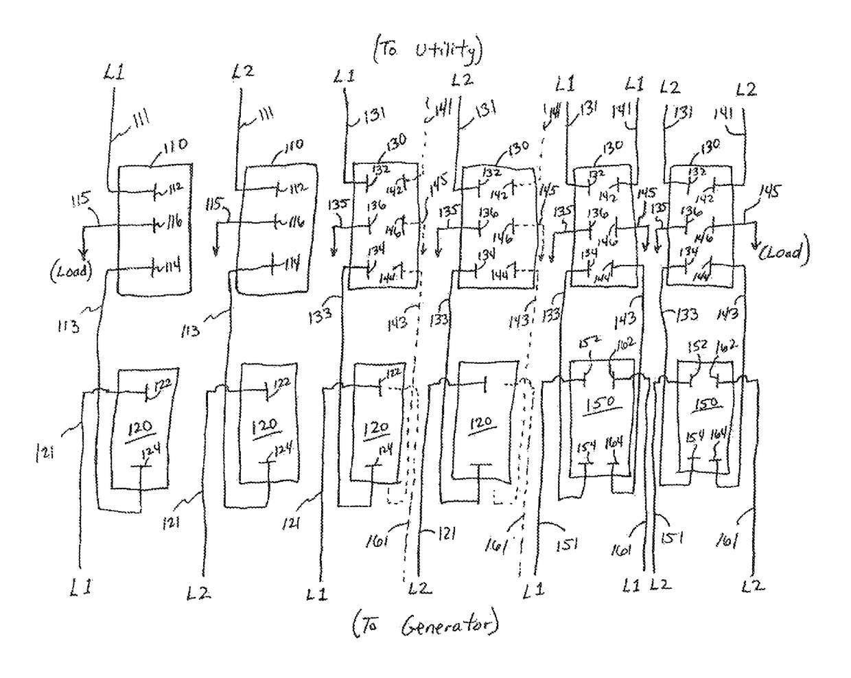
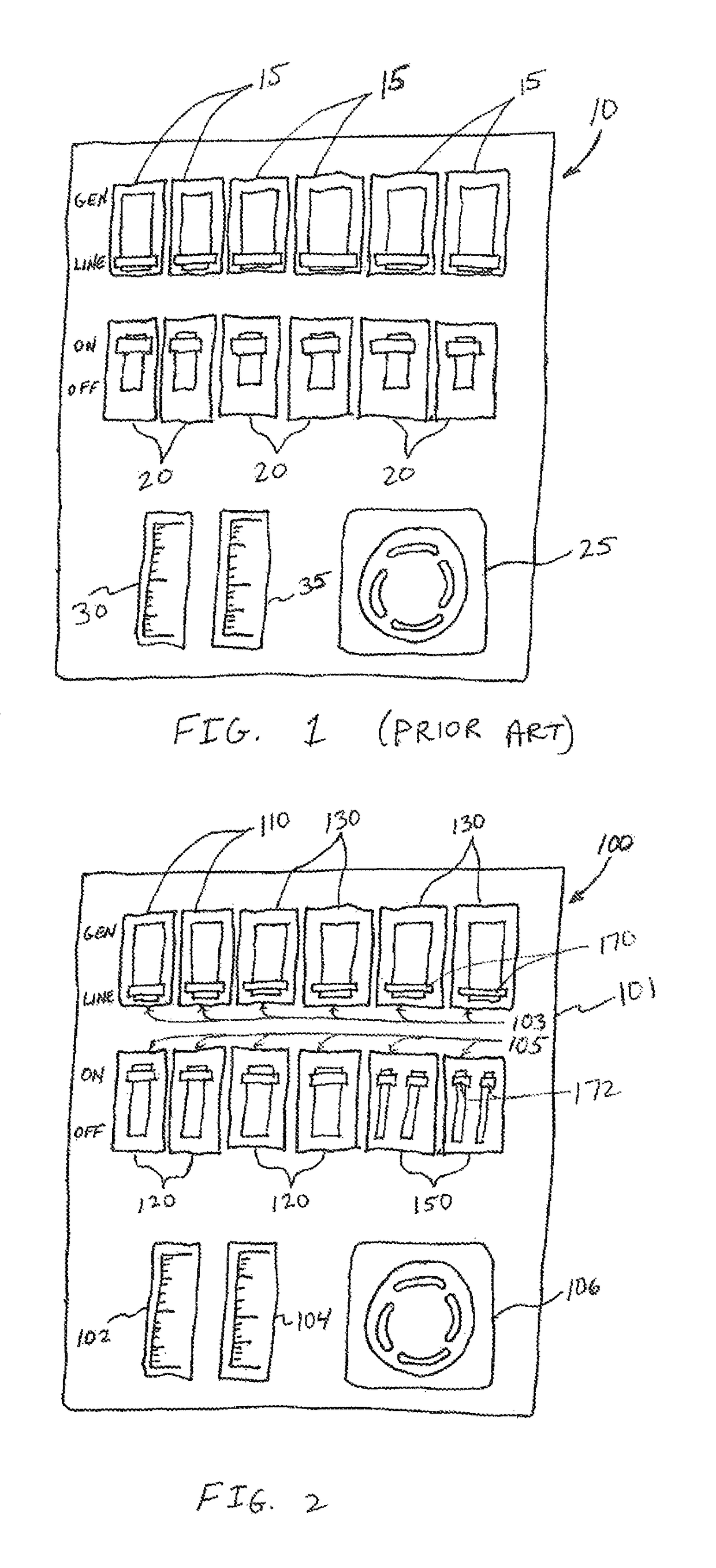
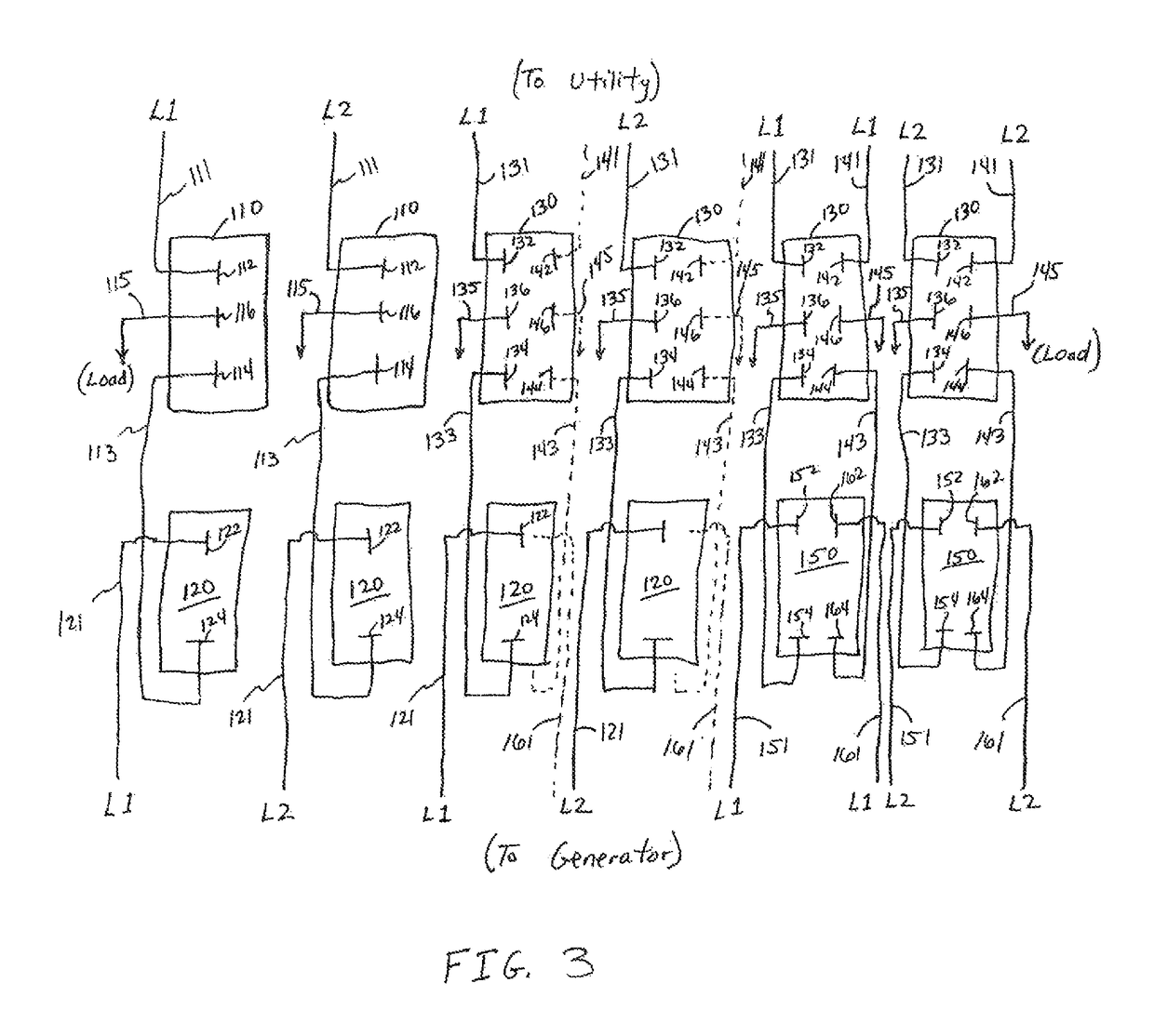
[0021]Turning initially to FIG. 2, a switching device 100 in accordance with ...


PUM


Abstract

A switching device includes multiple switches configured to selectively connect one of two power sources to electrical loads. The switching device may include either single-pole or double-pole, double-throw switches and corresponding single or double circuit breakers. The single and double circuit breakers are each configured to be inserted into openings having the same physical dimensions. At least one of the switches is a double-pole, double-throw switch, allowing two branch circuits to be transferred between power sources via the switch. A double breaker corresponding to the double-pole, double-throw transfer switch permits each of the branch circuits being switched by the double-throw switch to be wired through a separate protective circuit.

Description

CROSS-REFERENCE TO RELATED APPLICATIONS[0001]This application claims priority to U.S. provisional application Ser. No. 61 / 794,475, filed Mar. 15, 2013, the entire contents of which is incorporated herein by reference.BACKGROUND OF THE INVENTION[0002]The subject matter disclosed herein relates to a switching device configured to switch multiple electrical circuits between two power sources, and more specifically, to a switching device including a double pole, double throw switch operatively connected with a double circuit breaker to selectively connect one of two power sources to electrical loads.[0003]It is known that utility power lines are exposed to harsh environmental conditions and can become inoperable for many reasons, such as inclement weather, ice, falling trees, or animal damage, which may cause a portion of the power grid to fail or blackout. Consequently, many utility power customers install a backup generator to power some or all of the electrical loads present at the r...

Claims


Application Information

Patent Timeline
IPC IPC(8): H02J7/00H02J9/06H02J3/00H02J9/00H02J9/04H01H73/00
CPCH02J9/066H02J3/005H02J9/00H02J9/06H02J9/04H01H73/00H01H89/06H01H2300/018
Inventor FLEGEL, MICHAEL O.
Owner RELIANCE CONTROLS
Why Eureka
Try Eureka