Computing camera parameters

a camera and parameter technology, applied in the field of computer programs and systems, can solve problems such as inability to estimate with sufficient accuracy, deterioration of texturing process, and corrupted camera trajectory estimation

Active Publication Date: 2018-02-06
DASSAULT SYSTEMES
View PDF32 Cites 18 Cited by
  • Summary
  • Abstract
  • Description
  • Claims
  • Application Information

AI Technical Summary

Problems solved by technology

Obviously, any bias on the camera pose translates onto the re-projection and deteriorates the texturing process.
Such a bias is usual particularly significant in the case of depth-map analysis methods.
It generally originates from a shift in synchronizing between the depth sensor and the RGB sensor, corrupting the camera trajectory estimation.
But it may also originate from an outside shot from an independent camera whose relative position to the 3D model cannot be estimated with sufficient accuracy because there is no rigid dependency to the depth sensor.

Method used


Image

  • Computing camera parameters
  • Computing camera parameters
  • Computing camera parameters

Examples


Embodiment Construction

[0043]A description of example embodiments of the invention follows.

[0044]The teachings of all patents, published applications and references cited herein are incorporated by reference in their entirety.

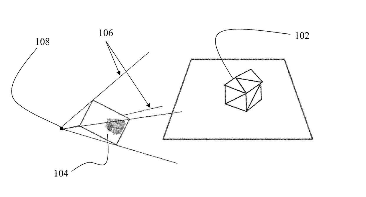
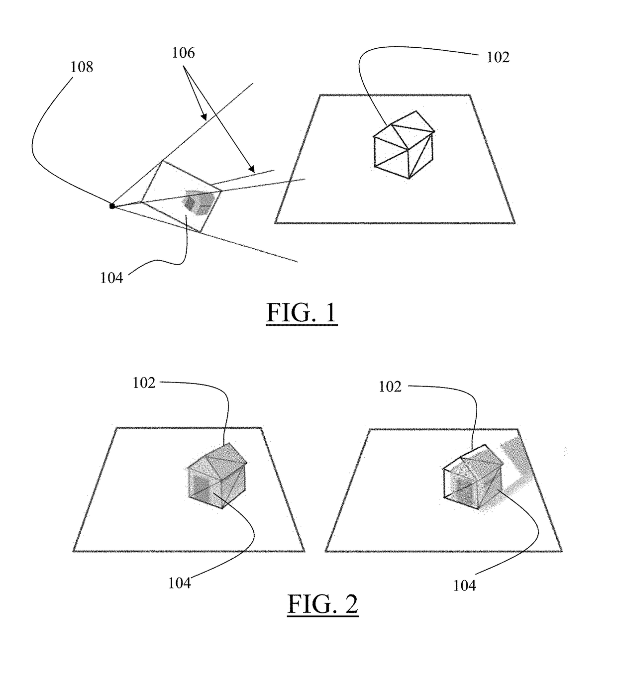
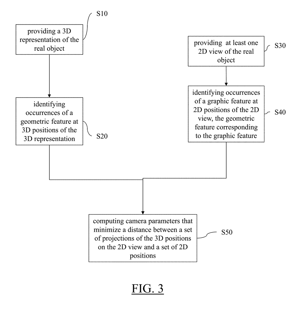
[0045]With reference to the flowchart of FIG. 3, it is proposed a computer-implemented method for designing a 3D modeled object. The 3D modeled object designed by the method represents a real object. The method comprises the step of providing S10 a 3D representation of the real object. The method also comprises the step of identifying S20 occurrences of a geometric feature at 3D positions of the 3D representation. The method also comprises the step of providing S30 at least one 2D view of the real object. The method also comprises identifying S40 occurrences of a graphic feature at 2D positions of the 2D view. The geometric feature corresponds to the graphic feature. The method eventually comprises computing S50 camera parameters that minimize a distance between a set of projections ...


PUM


Abstract

The invention notably relates to a computer-implemented method for designing a 3D modeled object representing a real object. The method comprises the steps of providing a 3D representation of the real object, identifying occurrences of a geometric feature at 3D positions of the 3D representation, providing at least one 2D view of the real object, identifying occurrences of a graphic feature at 2D positions of the 2D view, the geometric feature corresponding to the graphic feature, computing camera parameters that minimize a distance between a set of projections of the 3D positions on the 2D view and a set of 2D positions. This provides an improved solution for designing a 3D modeled object representing a real object.

Description

RELATED APPLICATION(S)[0001]This application claims priority under 35 U.S.C. § 119 or 365 to European Application No. EP13306576.3, filed Nov. 18, 2013. The entire teachings of the above application(s) are incorporated herein by reference.FIELD OF THE INVENTION[0002]The invention relates to the field of computer programs and systems, and more specifically to a method, system and program for designing a 3D modeled object representing a real object.BACKGROUND OF THE INVENTION[0003]A number of systems and programs are offered on the market for the design, the engineering and the manufacturing of objects. CAD is an acronym for Computer-Aided Design, e.g. it relates to software solutions for designing an object. CAE is an acronym for Computer-Aided Engineering, e.g. it relates to software solutions for simulating the physical behavior of a future product. CAM is an acronym for Computer-Aided Manufacturing, e.g. it relates to software solutions for defining manufacturing processes and ope...

Claims


Application Information

Patent Timeline
Patent Type & Authority Patents(United States)
IPC IPC(8): G06F17/50G06T7/80G06T17/00G06T15/04G06T17/10G06T7/73
CPCG06F17/50G06F17/5004G06F17/5086G06T7/75G06T7/80G06T15/04G06T17/10G06T17/00G06T2207/30244G06T2200/04G06T2200/08G06T2207/10024G06T2207/10028G06F30/17G06F30/13G06F30/00
Inventor MEHR, ELOIGUITTENY, VINCENTBOUFARGUINE, MOURAD
Owner DASSAULT SYSTEMES
Why Eureka
Try Eureka