3D push pull chain

a push-pull chain and chain technology, applied in the direction of chain elements, friction gearings, gearings, etc., can solve the problems of affecting the use of push-pull chains often requires more space, and the chain can transmit traction forces. , to achieve the effect of greater storage leeway and more flexibility

Active Publication Date: 2018-02-20
IWIS ANTRIEBSSYST
View PDF21 Cites 7 Cited by
  • Summary
  • Abstract
  • Description
  • Claims
  • Application Information

AI Technical Summary

Benefits of technology

[0004]Hence, the purpose of the present invention consists of providing a push pull chain of the type mentioned initially, which can be used more flexibly and which allows for a greater storage leeway.
[0006]Thanks to this distribution, the push pull chain can be divided for example into a driven part and an operational part which are guided towards each other in a different twisting direction in relation to the longitudinal chain axis. Hence, the chain can not only be guided and rolled up in one plane, but be positioned at least in two different planes. The level of flexibility of a push pull chain has been two-dimensional up to present. Through the proposed solution, the level of flexibility of the push pull chain is extended by at least one dimension in a thrust and traction direction. This enables the implementation of complex kinematic structures. The flows of force in these kinematics can be transmitted in traction as well as in thrust directions. Especially the compactness of drives for the push pull chain is extended by one dimension as the storage of the push pull chain in a drive is now independent of the operational direction of the chain. For example, the operational direction could be aligned perpendicularly to the roll-up or insertion plane of the push pull chain in the drive.
[0009]The linking piece can conveniently have a first junction point for the connection with the first chain section and a second junction point for the connection with the second chain section and the junction points can twist the first and the second chain section in an angle ranging from 30° to 150°, preferably 60° to 120°, especially 90°, towards each other. Therefore, it can be adapted to the particular drive situation and the suitable angle can be chosen whereby the angle of 90° has a special significance.
[0015]Besides, the invention also refers to a chain drive with a push pull chain according to one of the claims 1 to 9, a drive that meshes with the first chain section and a deflector system that meshes with the second or further chain section and that deflects the second or further chain section. The push pull chain is used as a 3D chain and can consequently be deflected and / or guided in two different spatial planes. This offers the possibility, for example, to arrange the chain section that interacts with the drive in a space-efficient manner so that less voluminous structures are required. This enables, for instance, the installation in a plane that is arranged perpendicularly to the operating direction of a second or further chain section.

Problems solved by technology

Of course, these chains can usually also transmit traction forces.
The use of push pull chains occasionally requires more space especially if the chain is to be rolled up for the purpose of storage or for the drive.
In some cases, this space requirement hampers the use of push pull chains.

Method used


Image

  • 3D push pull chain
  • 3D push pull chain
  • 3D push pull chain

Examples


Embodiment Construction

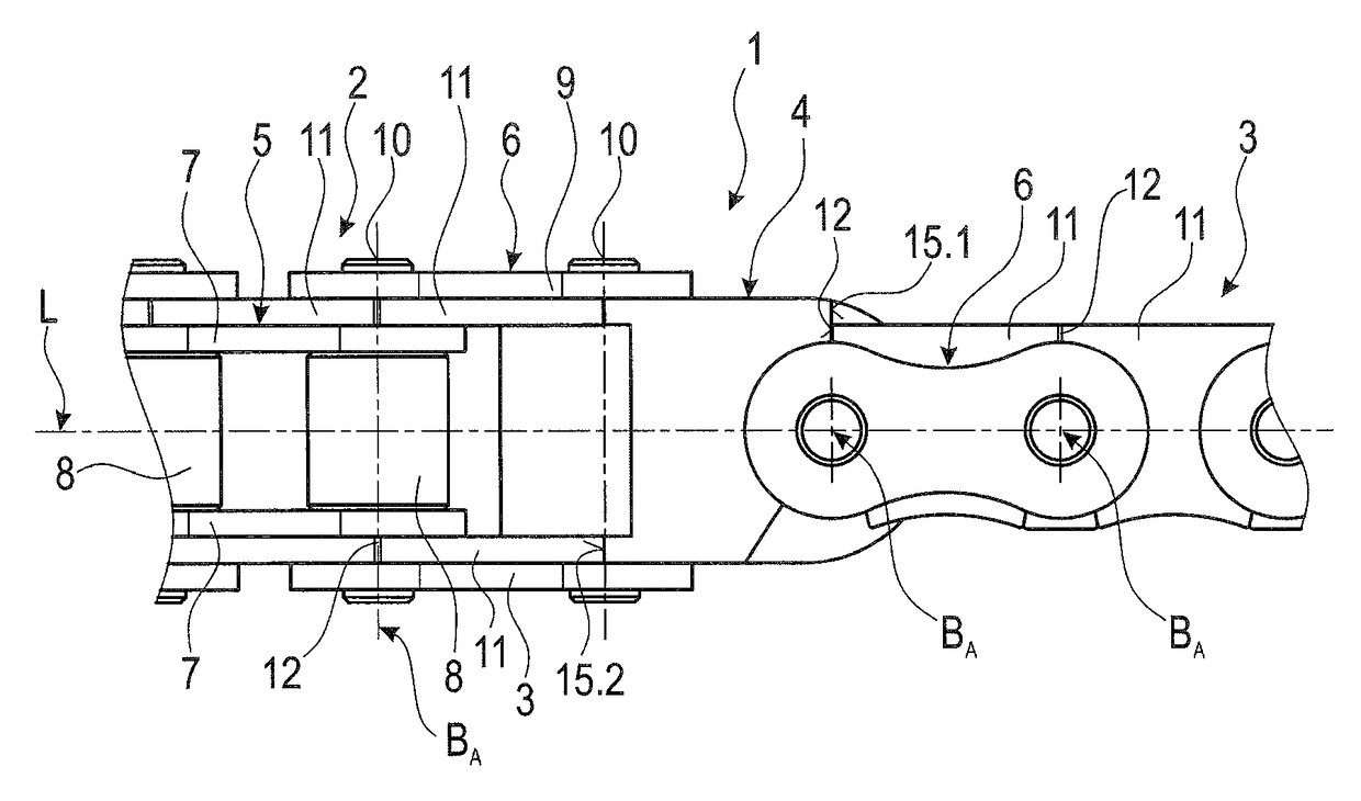
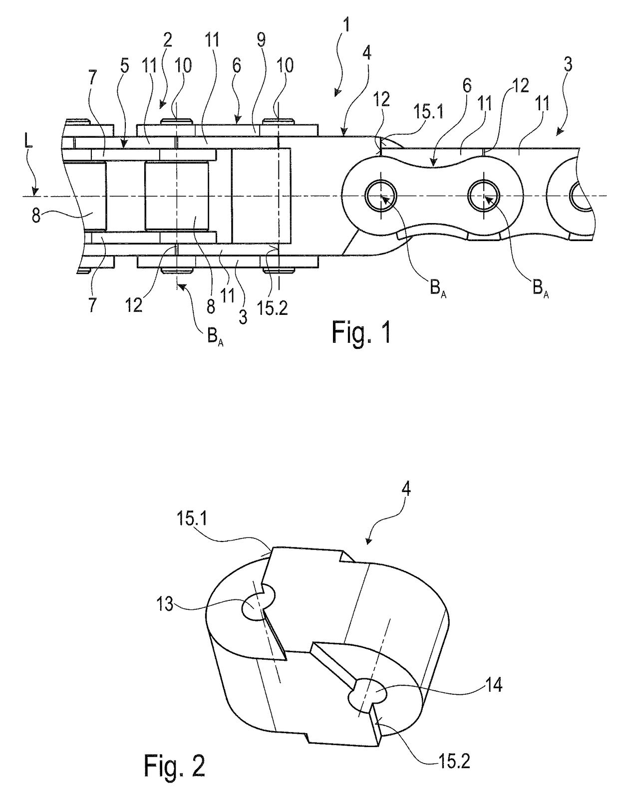
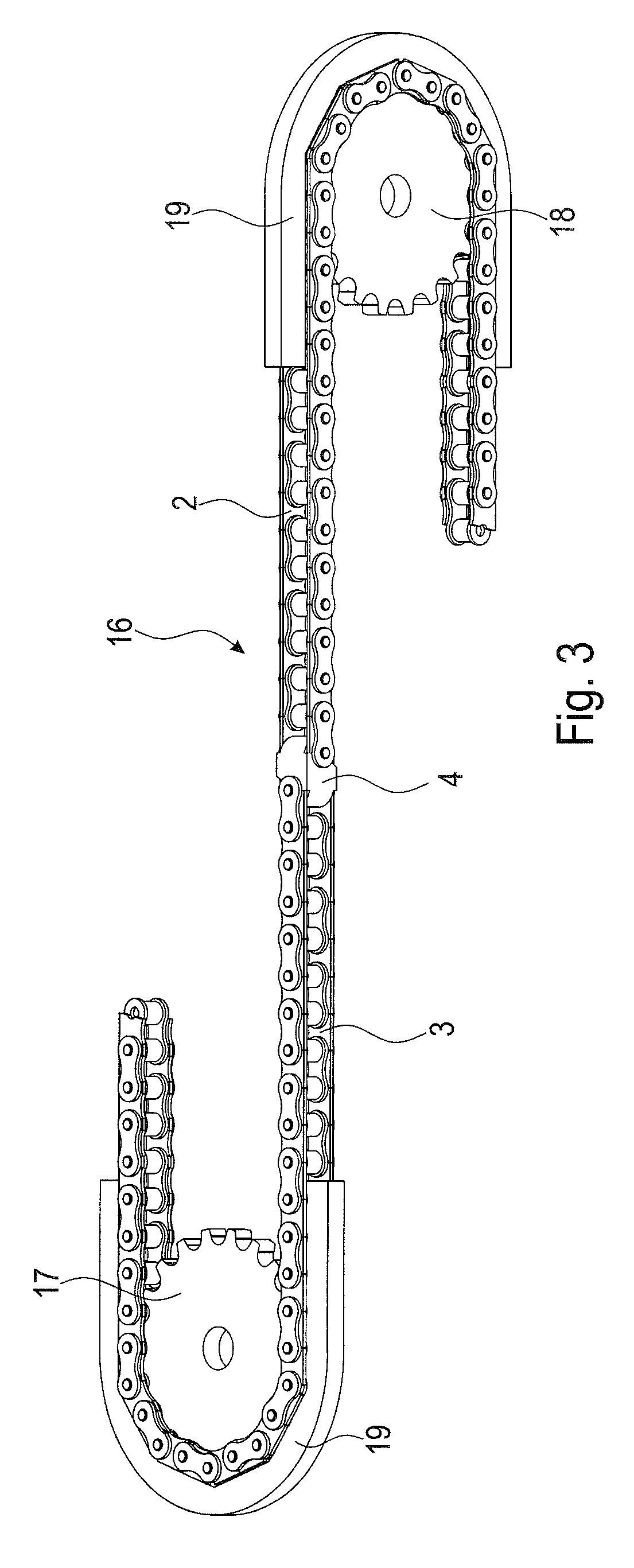
[0024]The push pull chain 1 shown in FIG. 1 comprises a first chain section 2 and a second chain section 3 that are connected to each other in a twisted way around the longitudinal axis L of the push pull chain 1 by means of a linking piece 4 installed in between.

[0025]The first and the second chain section 2 and 3 respectively consist of alternatingly interconnected internal and external chain links 5 and 6.

[0026]Each internal chain link 5 consists of two internal plate links 7 arranged in parallel and two plate links, not shown in the figure, that connect these plate links with each other. A roll 8 is installed rotatably on each of the sleeves.

[0027]Each external chain link 6 consists of external plate links 9 that are arranged in parallel and at a distance to each other and of chain bolts 10, installed in the spacing division of the chain 1, that connect these plate links to each other. Therefore, the chain bolts 10 are pressed into the external plate links 9 in appropriate apert...


PUM


Abstract

A push pull chain is provided with chain links that are connected to each other by respectively one chain joint, designed in a space-efficient manner. The chain joints of a first chain section with their joint axes have a first orientation, whereby the joint axes of the chain joints of a second chain section are arranged in a second orientation that is twisted around the longitudinal axis of the push pull chain or whereby they can be set to this orientation. In addition, a pertaining chain drive is provided.

Description

CROSS-REFERENCE TO RELATED APPLICATION[0001]This application claims priority to foreign European patent application No. EP 14001818.5, filed on May 23, 2014, the disclosure of which is incorporated by reference in its entirety.FIELD OF THE INVENTION[0002]The present invention concerns a push pull chain with chain links that are connected to each other respectively by one chain joint.BACKGROUND[0003]Push pull chains can be found in diverse forms in the state of the art. In most cases, they are plate-link chains with alternating internal and external chain links that are connected by means of a chain joint. The internal and / or external plate links or special stiffening brackets (links) are shaped in a way that the chain can be made bend-proof in one swivel direction of the chain joint. This is ensured for a lineally guided (straight) chain or slightly over-swiveled chain joints so that thrust powers can be subsequently transmitted. The chain joints can still be swiveled in the other s...

Claims


Application Information

Patent Timeline
Patent Type & Authority Patents(United States)
IPC IPC(8): F16H19/00F16G13/07F16G15/00F16H19/06F16G13/20
CPCF16H19/0645F16G13/07F16G15/00F16G13/20Y10T74/20Y10T74/1884F16G15/12
Inventor HARTINGER, GERHARDSAHIN, ORHAN
Owner IWIS ANTRIEBSSYST
Why Eureka
Try Eureka