
Three-dimensional magnetic flux leakage imaging detector in multi-section combined pipeline
A combination and detector technology, which is applied in the direction of instruments, measuring devices, and measuring distances, can solve the problems of detectors not working properly, slow propulsion speed, and small flow, so as to avoid equipment malfunctioning, improve battery life, The effect of improving reliability
- Summary
- Abstract
- Description
- Claims
- Application Information
AI Technical Summary
Problems solved by technology
Method used
Image

Examples
Embodiment Construction
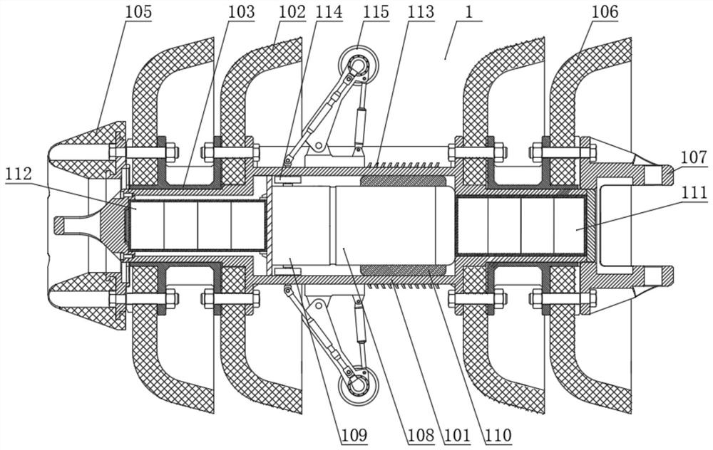
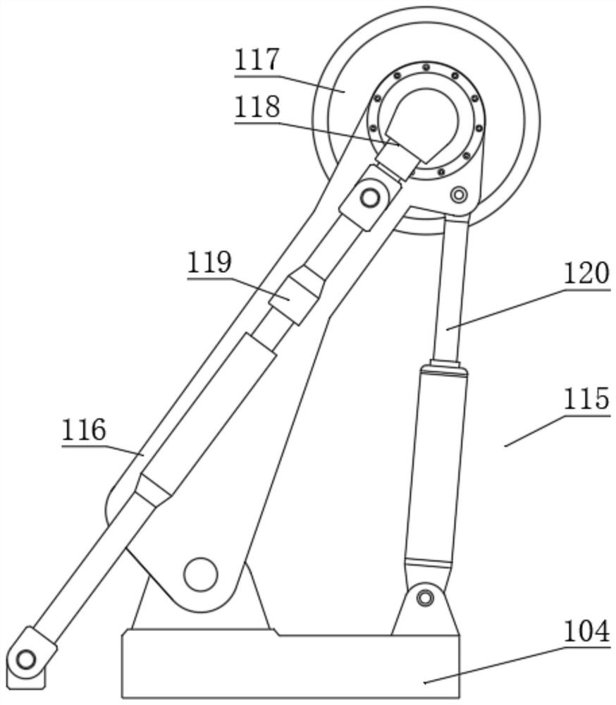
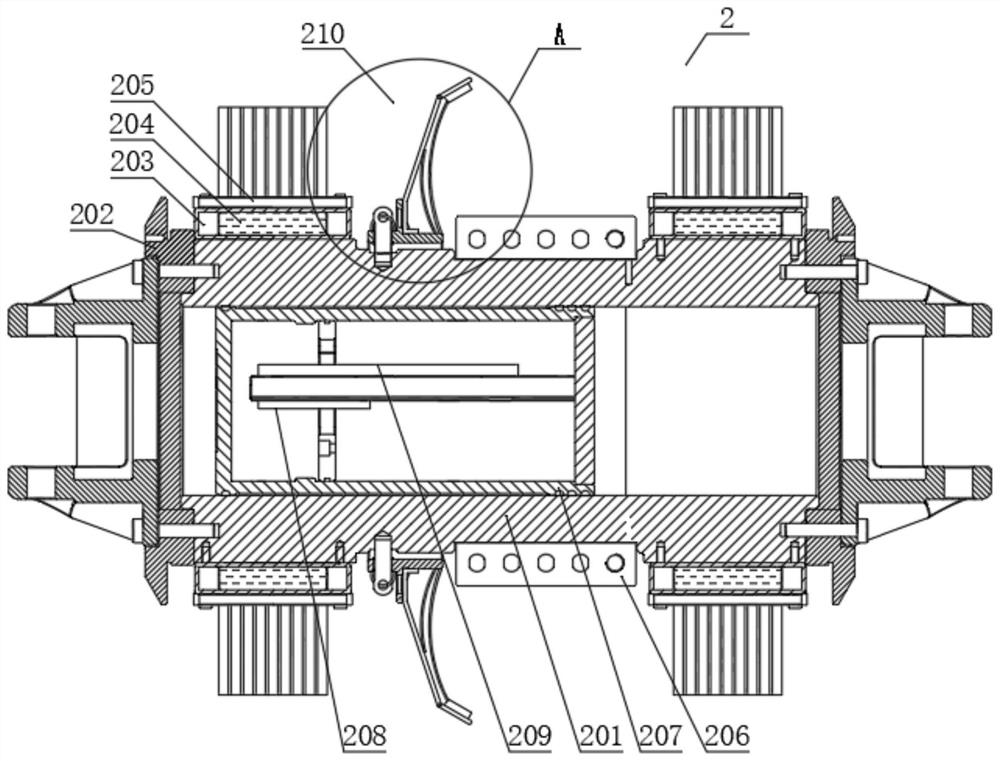
[0031] The multi-section combined three-dimensional magnetic flux leakage imaging detector in the pipeline includes a drive section assembly 1, a detection section assembly 2, an IO / DO detection section assembly 3, and a mileage wheel assembly 4, which are sequentially connected along the advancing direction of the detector. The second end of 1 and the second end of the detection section assembly 2 are hinged with a coupling assembly 5, such as Figure 8 As shown, the coupling assembly 5 includes a coupling rod 501 and two coupling housings 502, a first pin hole 503 is opened on the top of one end of the coupling housing 502, and a first pin hole 503 is opened on the side of the other end of the coupling housing 502. There is a second pin hole 504, the first pin hole 503 and the second pin hole 504 are perpendicular to each other, the second pin holes 504 of the two coupling seats 502 are all pierced with a pin shaft and connected to the connecting shaft through the pin shaft ...
PUM
 Abstract
Description
Claims
Application Information