Dipper door trip assembly

a technology of dipper and dipper, which is applied in the field of mining machines, can solve the problems of significant friction and wear on the surface of the latch bar and the latch keeper, and the movement of the latch bar generates significant friction and wear

Active Publication Date: 2018-03-13
JOY GLOBAL SURFACE MINING INC
View PDF39 Cites 3 Cited by
  • Summary
  • Abstract
  • Description
  • Claims
  • Application Information

AI Technical Summary

Problems solved by technology

Movement of the latch bar generates significant amounts of friction and wear on surfaces of the latch bar and latch keeper as the latch bar slides in and out of the latch keeper.
Thus, current dipper door trip mechanisms employ use of expensive, exotic, high strength materials on the latch bar and / or latch keeper to try and withstand some of the high amounts of friction and wear.

Method used


Image

  • Dipper door trip assembly
  • Dipper door trip assembly
  • Dipper door trip assembly

Examples


Embodiment Construction

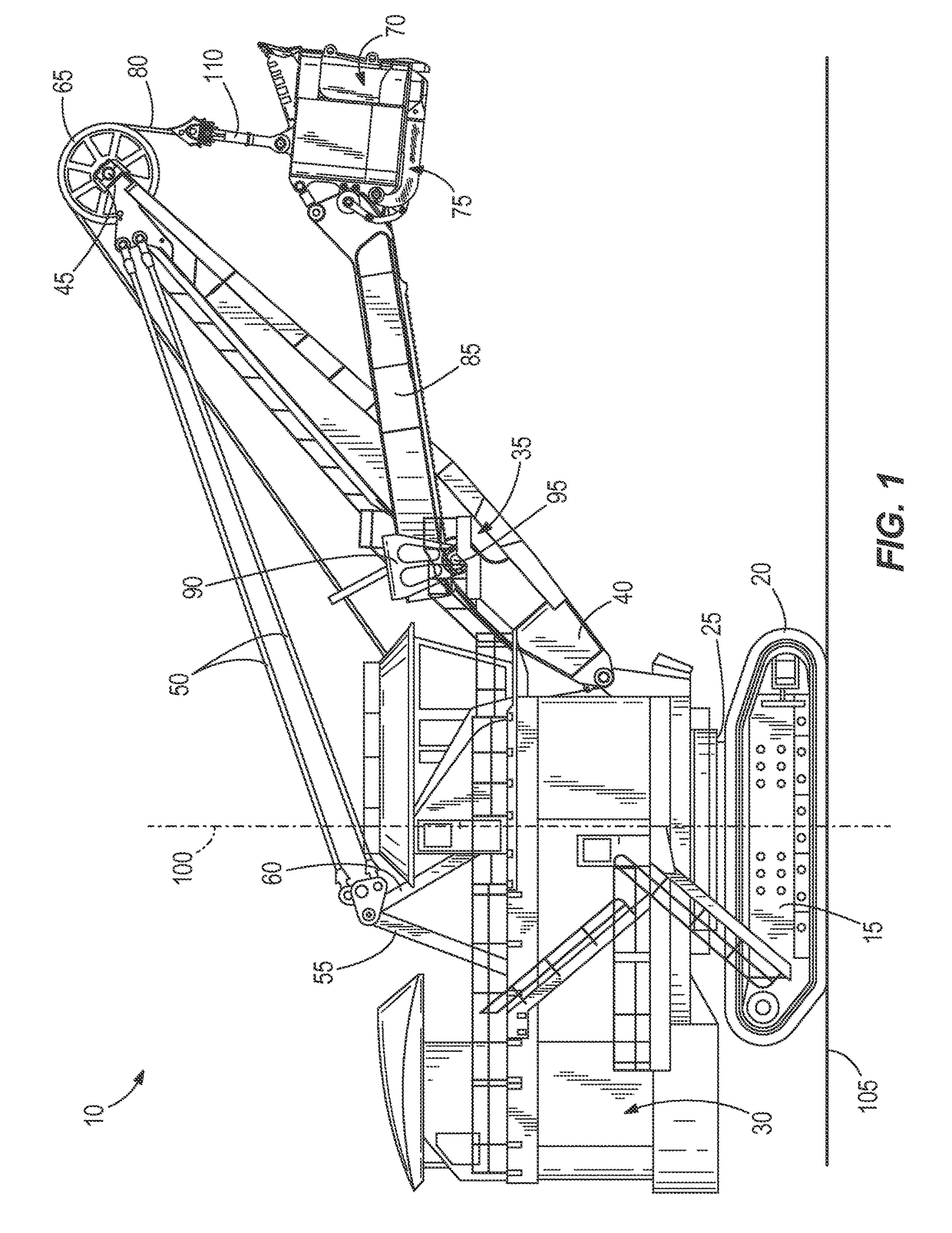
[0016]FIG. 1 illustrates a power shovel 10. The shovel 10 includes a mobile base 15, drive tracks 20, a turntable 25, a revolving frame 30, a boom 35, a lower end 40 of the boom 35 (also called a boom foot), an upper end 45 of the boom 35 (also called a boom point), tension cables 50, a gantry tension member 55, a gantry compression member 60, a sheave 65 rotatably mounted on the upper end 45 of the boom 35, a dipper 70, a dipper door 75 pivotally coupled to the dipper 70, a hoist rope 80, a winch drum (not shown), a dipper handle 85, a saddle block 90, a shipper shaft 95, and a transmission unit (also called a crowd drive, not shown). The turntable 25 allows rotation of the upper frame 30 relative to the lower base 15. The turntable 25 defines a rotational axis 100 of the shovel 10. The rotational axis 100 is perpendicular to a plane 105 defined by the base 15 and generally corresponds to a grade of the ground or support surface.

[0017]The mobile base 15 is supported by the drive tr...


PUM


Abstract

A dipper door trip assembly includes a dipper, a dipper door pivotally coupled to the dipper, a linkage assembly including a sliding latch bar disposed at least partially in the dipper door, and a latch keeper coupled to the dipper. The latch keeper includes a roller that engages and disengages the latch bar.

Description

CROSS-REFERENCE TO RELATED APPLICATIONS[0001]This application claims priority to U.S. Provisional Application No. 61 / 912,963, filed Dec. 6, 2013, the entire contents of which are incorporated herein by reference.BACKGROUND OF THE INVENTION[0002]The present invention relates to the field of mining machines. Specifically, the present invention relates to a dipper door and a dipper door trip assembly on a mining machine, such as a rope shovel.[0003]Industrial mining machines, such as electric rope or power shovels, draglines, etc., are used to execute digging operations to remove material from a bank of a mine. On a conventional rope shovel, a dipper is attached to a handle, and the dipper is supported by a cable, or rope, that passes over a boom sheave. The rope is secured to a bail that is pivotably coupled to the dipper. The handle is moved along a saddle block to maneuver a position of the dipper. During a hoist phase, the rope is reeled in by a winch in a base of the machine, lift...

Claims


Application Information

Patent Timeline
Patent Type & Authority Patents(United States)
IPC IPC(8): E02F3/407E21C27/30E02F3/30E02F3/46E21C47/00
CPCE02F3/4075E02F3/304E21C47/00E02F3/46E21C27/30E02F3/308E02F3/04E02F3/28
Inventor GROSS, MATTHEW L.NICOSON, RICHARD L.
Owner JOY GLOBAL SURFACE MINING INC
Why Eureka
Try Eureka