Control apparatus, image pickup apparatus, image pickup system, lens apparatus, control method, and non-transitory computer-readable storage medium
a control apparatus and image pickup technology, applied in the field of compound eye image pickup apparatus, can solve the problems of deteriorating accuracy of af control in other optical systems having different depth of field, increasing load in performing af control, and achieving efficient and accurate determination of focal points
- Summary
- Abstract
- Description
- Claims
- Application Information
AI Technical Summary
Benefits of technology
Problems solved by technology
Method used
Image
Examples
embodiment 1
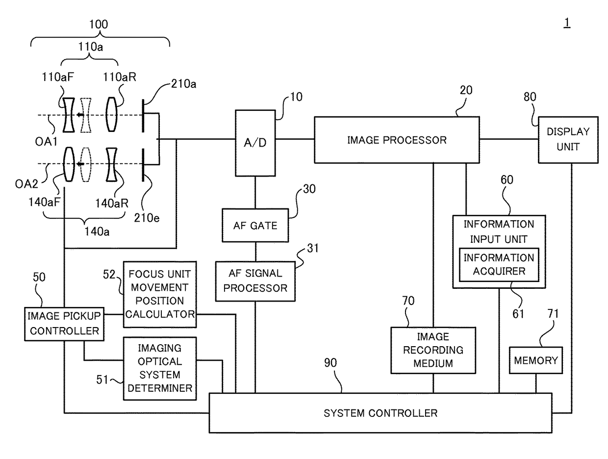
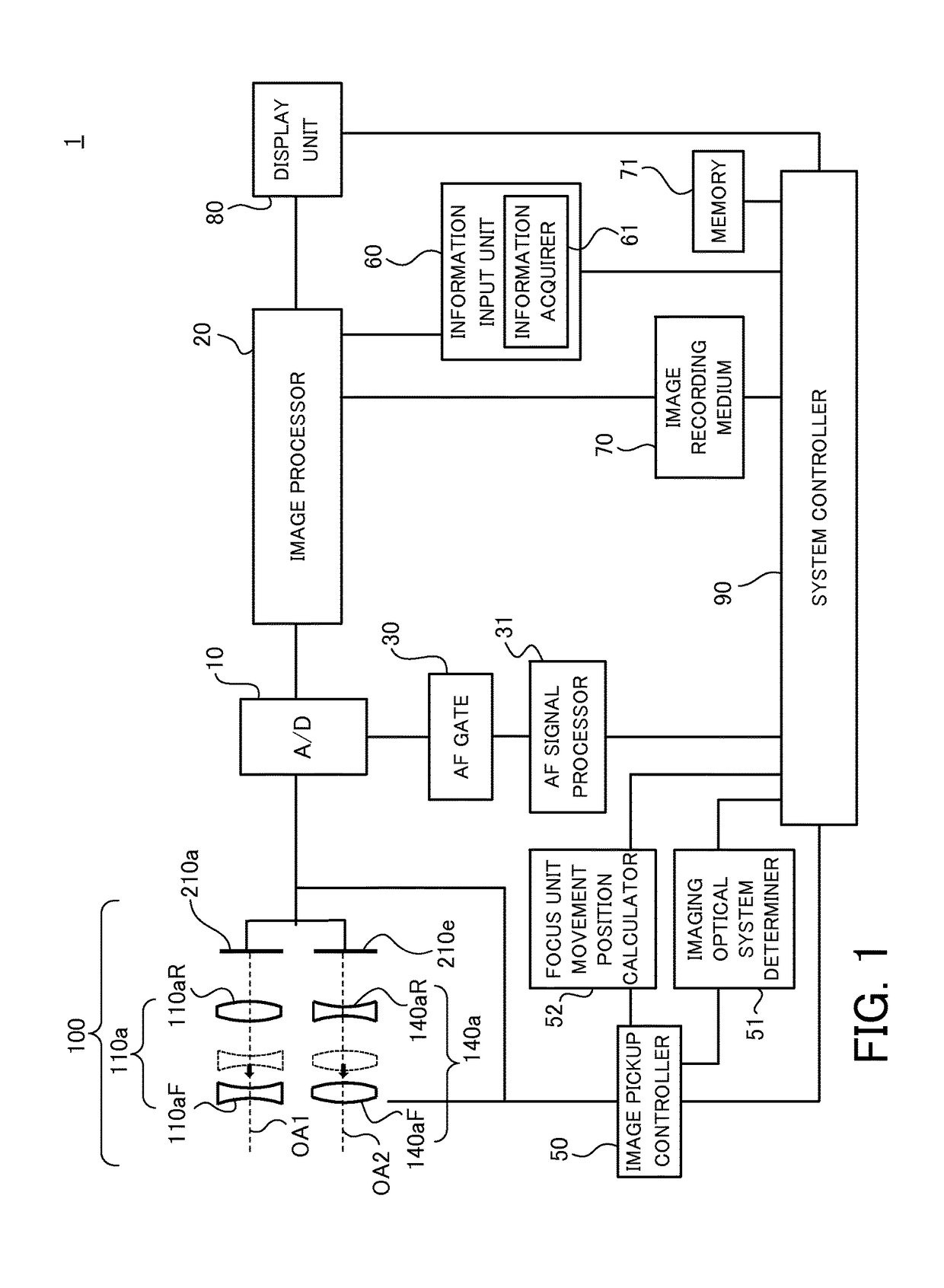
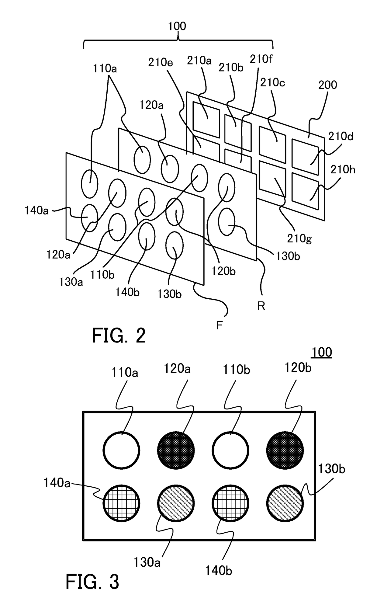
[0050]First of all, referring to FIGS. 1 to 3, a compound-eye image pickup apparatus in Embodiment 1 of the present invention will be described. FIG. 1 is a block diagram of a compound-eye image pickup apparatus 1 in this embodiment. FIG. 2 is a perspective view of an image pickup unit 100 in the compound-eyen image pickup apparatus 1. FIG. 3 is a front view of the image pickup unit 100.
[0051]The compound-eye image pickup apparatus 1 includes the image pickup unit 100, an A / D converter 10, an image processor 20, an AF gate 30, an AF signal processor 31 (focus detector), a system controller 90, and an image pickup controller 50 (controller). Furthermore, the compound-eye image pickup apparatus 1 includes an imaging optical system determiner 51 (determiner), a focus unit movement position calculator 52 (calculator), an information input unit 60, an information acquirer 61 (acquirer), an image recording medium 70, a memory 71, and a display unit 80. The compound-eye image pickup appara...
embodiment 2
[0081]Next, referring to FIG. 6, a compound-eye image pickup apparatus in Embodiment 2 of the present invention will be described. FIG. 6 is a block diagram of a compound-eye image pickup apparatus 2 in this embodiment. The compound-eye image pickup apparatus 2 of this embodiment is different from the compound-eye image pickup apparatus 1 of Embodiment 1 in that the compound-eye image pickup apparatus 2 includes a phase-difference AF gate 32 and a phase-difference AF signal processor 33, instead of the AF gate 30 and the AF signal processor 31.
[0082]The phase-difference AF gate 32 supplies, to the phase-difference AF signal processor 33 (focus detector), only a signal in a focus detection region or an AF frame set by the system controller 90 among output signals of all pixels from the A / D converter 10. The phase-difference AF signal processor 33 performs processing of a phase-difference detection method on a pixel signal (focal signal or image signal) supplied from the phase-differe...
embodiment 3
[0099]Next, referring to FIG. 8, a compound-eye image pickup apparatus in Embodiment 3 of the present invention will be described. FIG. 8 is a block diagram of a compound-eye image pickup apparatus 3 in this embodiment. The compound-eye image pickup apparatus 3 of this embodiment is different from the compound-eye image pickup apparatus 1 of Embodiment 1, the compound-eye image pickup apparatus 2 of Embodiment 2, or the combination of them in that the compound-eye image pickup apparatus 3 includes an information input unit 60a containing a focus detection region determiner 62 and a region inclusion determiner 63, instead of the information input unit 60.
[0100]The focus detection region determiner 62 (region determiner) determines, as a focus detection region, a region specified by a user via the information input unit 60a. The region inclusion determiner 63 (inclusion determiner) determines whether the focus detection region is included in each image signal obtained via an image pic...
PUM
 Abstract
Description
Claims
Application Information
 - R&D
- Intellectual Property
- Life Sciences
- Materials
- Tech Scout
- Unparalleled Data Quality
- Higher Quality Content
- 60% Fewer Hallucinations
Browse by: Latest US Patents, China's latest patents, Technical Efficacy Thesaurus, Application Domain, Technology Topic, Popular Technical Reports.
© 2025 PatSnap. All rights reserved.Legal|Privacy policy|Modern Slavery Act Transparency Statement|Sitemap|About US| Contact US: help@patsnap.com


