Crop harvesting machine

a harvesting machine and crop technology, applied in the direction of agricultural tools and machines, guiding agricultural machines, agriculture, etc., to achieve the effect of long evaluation tim

Active Publication Date: 2018-03-27
CLAAS E SYST GMBH
View PDF16 Cites 29 Cited by
  • Summary
  • Abstract
  • Description
  • Claims
  • Application Information

AI Technical Summary

Benefits of technology

[0009]Accordingly, the invention includes a second sensor arrangement that provides sensor information by detecting a space orientation of the machine body and / or the discharge spout, where the electronic spout control generates its drive commands for guiding the crop stream not only based on the sensor information of the first sensor arrangement, but also based on the sensor information of the second sensor arrangement. With this basic concept it is possible for the electronic spout control to react on a change in space orientation of the machine body and / or the discharge spout such that the impact of this change in space orientation on the crop stream may be minimized.
[0012]In another embodiment, the first sensor arrangement comprises a camera arrangement or a laser sensor arrangement in order to identify the respective reference feature at the trailer. Here the proposed solution shows another advantage. Due to the fact that optical sensor arrangements generally require a relatively long evaluation time, the update frequency of the sensor information provided to the electronic spout control is higher for the second sensor arrangement than for the first sensor arrangement. This means that a delay in acquiring the sensor information of the first sensor arrangement is compensated by the high update frequency of the sensor information for the second sensor arrangement.
[0013]In another embodiment, based on the sensor information of the second sensor arrangement, the drive track of the crop harvesting machine is determined. The first sensor arrangement now only searches for the reference feature in a search area, which search area is defined by the drive track (preferably in the drive track), of the crop harvesting machine. This makes it possible to exclude the surrounding of the drive track from searching, which prevents erroneously identifying a contour in the surrounding of the drive track as the reference feature.

Problems solved by technology

It is a challenging task to constantly align the discharge spout, such that the resulting crop stream does not miss the receiving area of the trailer.
Any change in driving direction puts a challenge to the automatic guidance of the discharge spout, as even small curves have a large impact on the actual hit point of the crop stream.

Method used


Image

  • Crop harvesting machine
  • Crop harvesting machine
  • Crop harvesting machine

Examples


Embodiment Construction

[0025]The following is a detailed description of example embodiments of the invention depicted in the accompanying drawing. The example embodiments are presented in such detail as to clearly communicate the invention and are designed to make such embodiments obvious to a person of ordinary skill in the art. However, the amount of detail offered is not intended to limit the anticipated variations of embodiments; on the contrary, the intention is to cover all modifications, equivalents, and alternatives falling within the spirit and scope of the present invention, as defined by the appended claims.

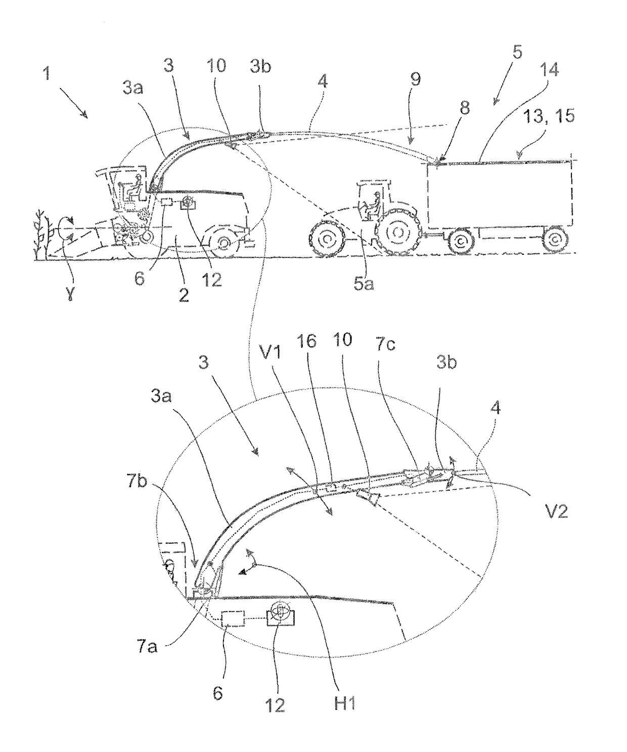
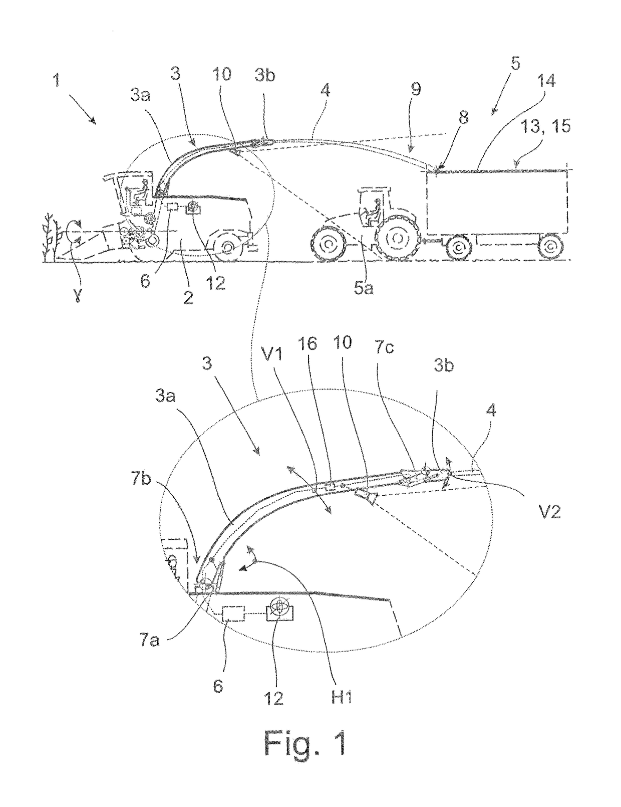
[0026]As disclosed herein, the proposed crop harvesting machine 1 may be of various designs, for example, a combine or a forage harvester. While those crop harvesting machines 1 are self-propelled machines, the invention may well be applicable to crop harvesting machines 1, that are being pulled by a tractor or the like.

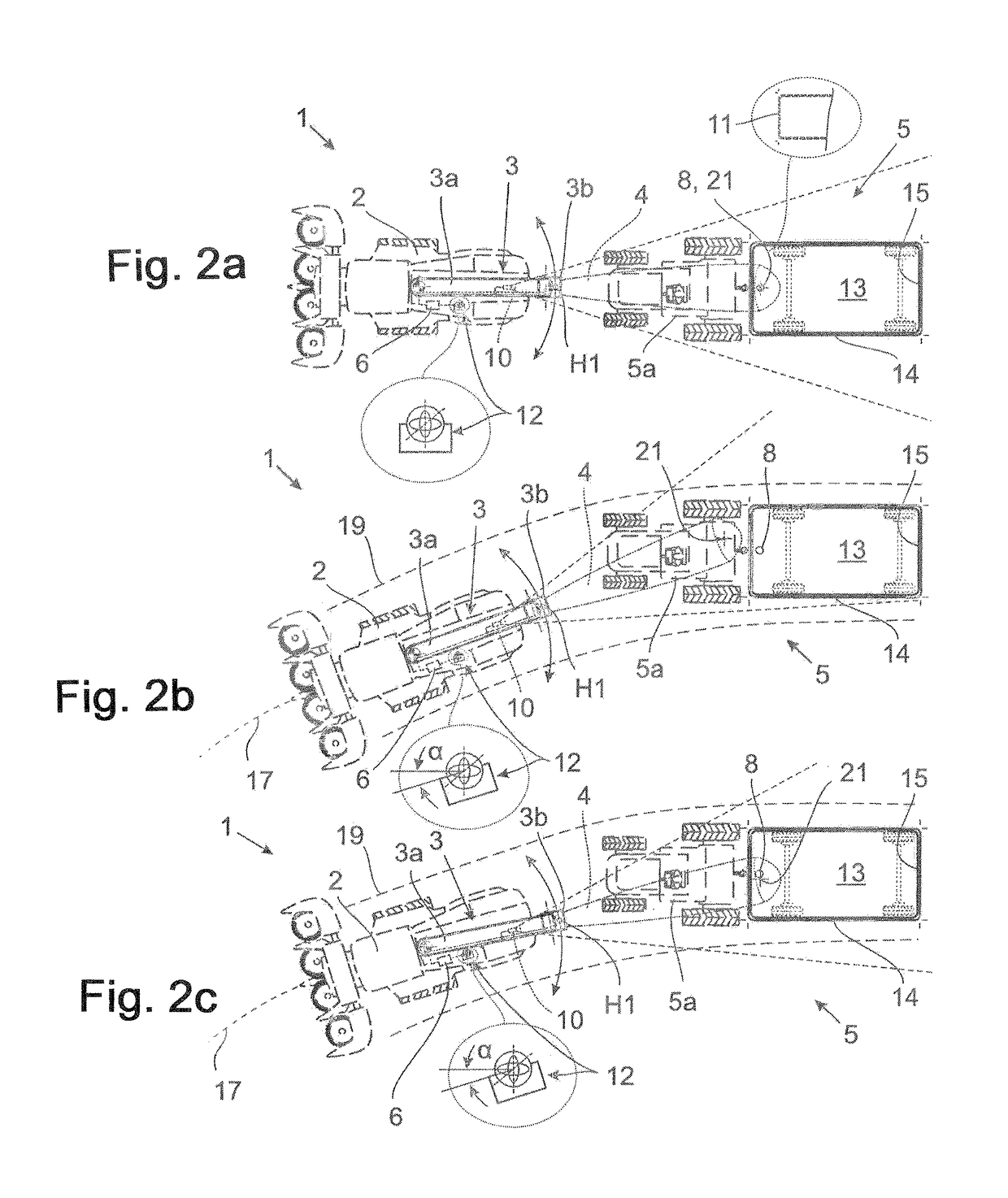
[0027]As shown, the crop harvesting machine 1 comprises a machine body 2...


PUM


Abstract

A crop harvesting machine has a machine body and a discharge spout attached to the machine body for overloading crop via a crop stream to a trailer. And electronic spout control and a discharge spout drive arrangement displaces the discharge spout relative to the machine body based on drive commands of the electronic spout control for guiding the crop stream to a target hit point at the trailer. A first sensor arrangement generates sensor information by optically identifying a reference feature at the trailer and detecting the position of the reference feature and / or space orientation of the reference feature. The second sensor arrangement generates sensor information by detecting a space orientation of the machine body, the discharge spout or both. The electronic spout control generates its drive commands for guiding the crop stream based on the sensor information.

Description

CROSS-REFERENCE TO A RELATED APPLICATION[0001]The invention described and claimed hereinbelow is also described in German Patent DE 10 2015 12 116 570.8, filed on Sep. 30, 2016. This German Patent Application, subject matter of which is incorporated herein by reference, provides the basis for a claim of priority of invention under 35 U.S.C. 119(a)-(d).BACKGROUND OF THE INVENTION[0002]The invention is directed to a crop harvesting machine that comprises a machine body and a discharge spout attached to the machine body for over loading crop via a crop stream to a trailer, requiring that the crop stream be guided into a receiving area of the trailer, which mostly is defined by an upper, open side of the trailer. A spout drive arrangement is assigned to the discharge spout such that the discharge spout is displaced relative to the machine body by transmitting drive commands to the discharge spout drive arrangement.[0003]It is a challenging task to constantly align the discharge spout, s...

Claims


Application Information

Patent Timeline
Patent Type & Authority Patents(United States)
IPC IPC(8): A01D90/10A01B69/04A01D43/08
CPCA01D90/10A01D43/087A01B69/008A01D41/00A01D41/04
Inventor LISOUSKI, PAVELKIRK, KRISTIANANDERSEN, GERT LYSGAARDBLAS, MORTEN RUFUSHARTMANN, RALFLAHMANN, DIRK
Owner CLAAS E SYST GMBH
Why Eureka
Try Eureka