
3-D printer

a printing device and three-dimensional technology, applied in the direction of manufacturing driving means, manufacturing tools, application layer means, etc., can solve the problems of limited mobility, large size and weight, and difficulty in adjusting and maintaining the levelness of the extrusion assembly plan

Active Publication Date: 2018-03-27
MARTIN MATTHEW H
View PDF2 Cites 0 Cited by
  • Summary
  • Abstract
  • Description
  • Claims
  • Application Information

AI Technical Summary

Benefits of technology

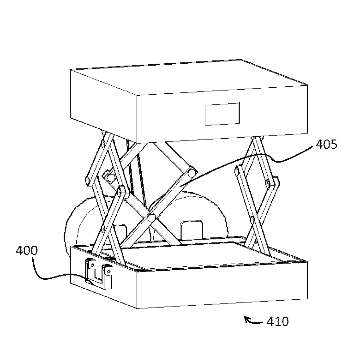
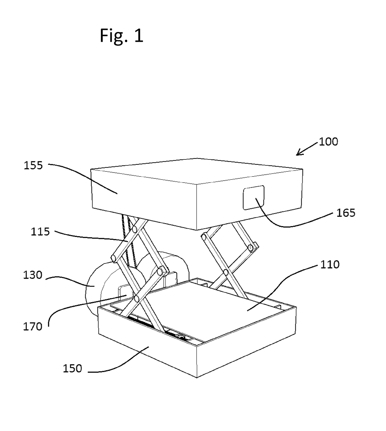
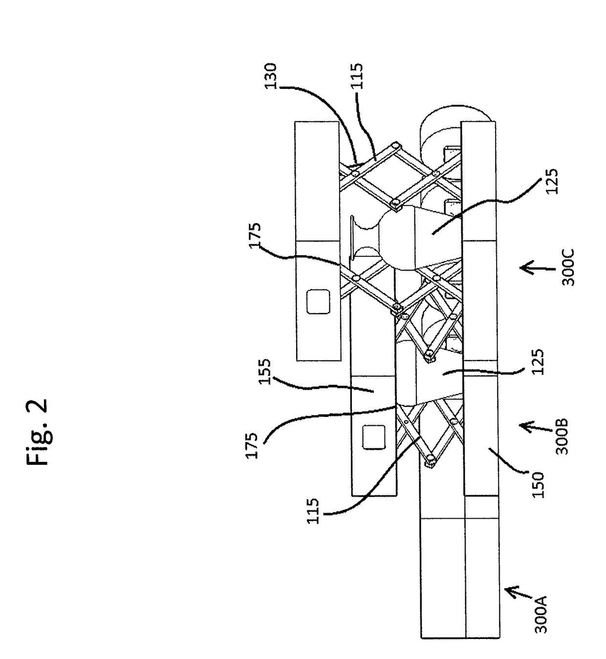
[0006]The present invention is a three dimensional printer that controls a vertical movement of an extruder assembly using scissor lift-type linkages that collapse and expand to several times their contracted height. This allows the 3D printer to be stored or transported in smaller containers, since the printer does not include a frame that encloses the maximum volume of the object to be printed. In the case of a personal 3D printer, it may be designed to fit in a convenient carry-all or suit case, and then when in use expand vertically to print taller objects. In the case of 3D printer used to build large concrete structures such as homes, it may be designed to fit on the back of truck trailer and expand to build multiple storied structures.
[0007]Gyroscopic, optical, or magnetic sensors may be incorporated into the 3D printer along with compensating mechanisms such as counterweights, hydraulics, motor control, or propellers. The levelness or desired orientation of the extruder assembly plane can be monitored and maintained with a computer that corrects such imperfections hundreds of times per second by finely adjusting the height of each vertical scissor lift or other compensation mechanism according to readings from the various sensors. This allows the 3D printer to function properly despite unevenness of the ground or unexpected changes in the environment.

Problems solved by technology

The limitations of this type of configuration include limited mobility, large size, and weight.
It's also sometimes difficult to adjust and maintain levelness of the extrusion assembly plane through the entire build operation.

Method used


Image

  • 3-D printer
  • 3-D printer
  • 3-D printer

Examples


Embodiment Construction

[0018]FIG. 1 shows an embodiment of a collapsible 3D printer 100. The system includes a base housing 150 containing various mechanical, electrical, and electronic components that operate the printer 100. An upper housing 155 is positioned above and parallel to the base housing 150 and houses the extruder assembly (not shown) as well as mechanical and electronic components that operate the printer 100. The upper housing 155 and the lower housing 150 are connected by collapsible scissor linkages 115 that allow the printer 100 to collapse and expand in the vertical direction while remaining parallel to each other. The build material 130 may be kept on spool brackets 170 and fed into the upper housing 155 and through the extruder system. The extruder system is movable along 2 perpendicular horizontal axes and deposits the material 130 onto the build platform 110. The material 130 is deposited onto the build platform 110 as the linkage 115 moves the upper housing 155 in the vertical dire...


PUM

PropertyMeasurementUnit
angleaaaaaaaaaa
heightaaaaaaaaaa
distanceaaaaaaaaaa

Abstract

A three-dimensional (3D) printing device has at least one collapsible vertical or horizontal axis using a scissor lift mechanism. One of the horizontal axis's can be made operable via a track or path where the entire machine moves along that path via movable wheels or gears. Sensors may monitor the height, orientation, position, and relative distance of the axes, machine, or extruders. Compensating mechanisms such as counterweights, propellers, or gyroscopes may be used to maintain balance, levelness, and control of the system. As a result, the size and weight of the 3D printer is reduced and made easier to transport while maintaining quality build functionality.

Description

TECHNICAL FIELD[0001]The present invention relates to a three dimensional (3D) printing device.BACKGROUND[0002]Three dimensional (3D) printing is a form of additive manufacturing also known as stereolithography (“STL”) or Fusion Deposition Method (FDM). Structures, parts, or items may be manufactured by building up successive layers of material which are either fused, adhered, or hardened together. A computer may control the movement and deposition of the desired material, which can be a malleable material such as plastic, through an extruder assembly. Many other materials, for example concrete (concrete like materials), chocolate (food products), rubber, nylon, electrically conductive resins, metals, and epoxy-like (resin hardeners) materials can also be used as well as other materials.[0003]Typically, the extruder assembly heats the material and extrudes it onto a printing surface or platform. The extruder assembly's movement may be controlled by a series of actuators, servo-motor...

Claims


Application Information

Patent Timeline
Patent Type & Authority Patents(United States)
IPC IPC(8): B29C67/00B29C64/20B29C64/209B29C64/236B29C64/227B33Y30/00B29C64/232B33Y40/00
CPCB29C67/20B29C64/227B29C64/232B29C64/236B29C64/209B33Y40/00B33Y30/00
Inventor MARTIN, MATTHEW H.
Owner MARTIN MATTHEW H
Learn More