Pluggable module having cooling channel

Active Publication Date: 2018-04-03
TYCO ELECTRONICS LOGISTICS AG (CH)
View PDF8 Cites 19 Cited by
  • Summary
  • Abstract
  • Description
  • Claims
  • Application Information

AI Technical Summary

Benefits of technology

[0005]In one embodiment, a pluggable module is provided having a pluggable body extending between a front end and a mating end. The mating end is receivable in a module cavity of the receptacle assembly to mate with the communication connector. The pluggable body has a top and channel walls extending above the top defining a cooling channel along the top. The cooling channel allows airflow between the front end and the mating end. The pluggable module includes a communication circuit board held in the pluggable body. The pluggable body is configured to be plugged into the receptacle assembly such that the communication circuit board is communicatively coupled to the communication connector of the receptacle assembly. The pluggable module includes an EMI shield coupled to the pluggable body above the top. The EMI shield has a shield plate spanning the cooling channel. The shield plate is metal and provides electrical shielding across the cooling channel. The shield plate has openings allowing airflow therethrough to flow through the cooling channel.
[0006]In another embodiment, a pluggable module is provided including a pluggable body extending between a front end and a mati

Problems solved by technology

However, as data speeds through the communication system increase, heat generated by the components is likewise increased.
Heat dissipa

Method used


Image

  • Pluggable module having cooling channel
  • Pluggable module having cooling channel
  • Pluggable module having cooling channel

Examples


Embodiment Construction

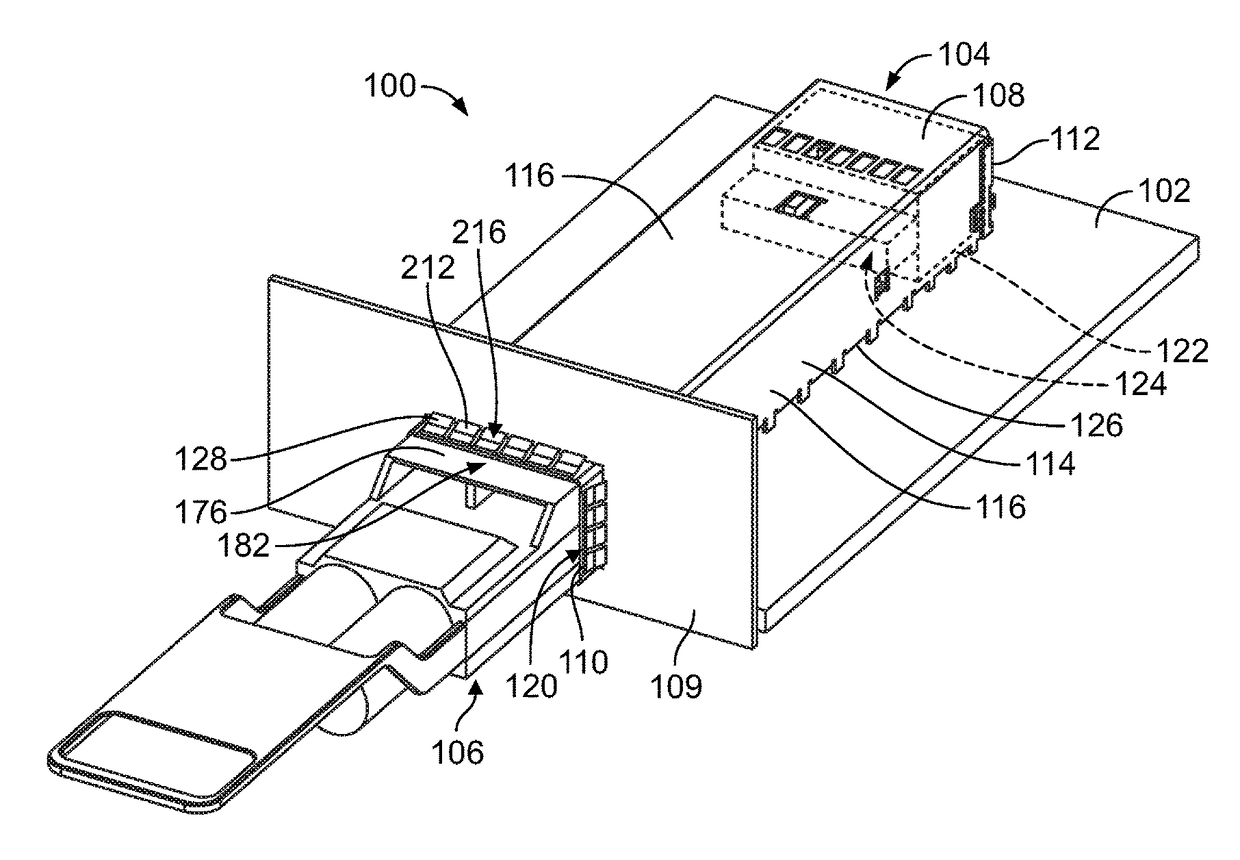
[0014]FIG. 1 is a front perspective view of a communication system 100 in accordance with an embodiment. The communication system 100 includes a circuit board 102, a receptacle assembly 104 mounted to the circuit board 102, and a pluggable module 106 that is configured to be received in the receptacle assembly 104. The circuit board 102 may be a daughter card or a mother board and include conductive traces (not shown) extending therethrough. Optionally, the pluggable module 106 may be communicatively coupled to the receptacle assembly 104, such as to a communication connector, to send and / or receive data signals with components of the communication system 100.

[0015]The communication system 100 may be part of or used with telecommunication systems or devices. For example, the communication system 100 may be part of or include a switch, router, server, hub, network interface card, or storage system. In the illustrated embodiment, the pluggable module 106 is configured to transmit data...


PUM


Abstract

A pluggable module includes a pluggable body having a top and channel walls extending above the top defining a cooling channel along the top. The cooling channel allows airflow between a front end and a mating end of the pluggable body. The pluggable module includes a communication circuit board held in the pluggable body. The pluggable module includes an EMI shield coupled to the pluggable body above the top. The EMI shield has a shield plate spanning the cooling channel. The shield plate is metal and provides electrical shielding across the cooling channel. The shield plate has openings allowing airflow therethrough to flow through the cooling channel.

Description

BACKGROUND OF THE INVENTION[0001]The subject matter herein relates generally to pluggable modules having cooling channels.[0002]At least some known communication systems include receptacle assemblies, such as input / output (I / O) connector assemblies, that are configured to receive a pluggable module and establish a communicative connection between the pluggable module and an electrical communication connector of the receptacle assembly. As one example, a known receptacle assembly includes a cage member that is mounted to a circuit board and configured to receive a small form-factor pluggable (SFP) transceiver in an elongated cavity of the cage member. The pluggable module and the electrical connector have respective electrical contacts that engage one another to establish a communicative connection.[0003]Electrical shielding of the components of the communication system is typically achieved using a receptacle housing or cage that provides shielding around the module cavity that rece...

Claims


Application Information

Patent Timeline
IPC IPC(8): H01R13/648H01R13/659H01R13/518H05K7/20H01R13/66
CPCH01R13/659H01R13/518H05K7/20127H05K7/20409H01R13/665H01R12/71H01R13/46H01R13/6581G02B6/4261G02B6/4268G02B6/4277H01R13/6583H05K9/0018H05K9/0058
Inventor BRIANT, ERIC DAVIDSHANKAR, NIKHIL
Owner TYCO ELECTRONICS LOGISTICS AG (CH)
Why Eureka
Try Eureka