
Press forming method

Active Publication Date: 2018-04-10
JFE STEEL CORP
View PDF5 Cites 0 Cited by
  • Summary
  • Abstract
  • Description
  • Claims
  • Application Information

AI Technical Summary

Benefits of technology

The present invention provides a press forming method that solves the problem of stretch flange cracking while maintaining product shape freedom. Additionally, the method is excellent in accurately shaping the top portion of the product, which is difficult to deform.

Problems solved by technology

In stretch flange forming, if the stretch deformation exceeds the deformation limit of the metal sheet, a crack is generated.
In particular, a stretch flange crack easily occurs in a formed part of a high-strength steel sheet, for example, a press formed part for an automobile.
If a stretch flange crack is generated, a prescribed part shape may not be obtained.

Method used


Image

  • Press forming method
  • Press forming method
  • Press forming method

Examples


working examples

[Working Examples]

[0078]In order to verify the effects of the present invention, the conventional method and the method of the present invention were tested by analysis according to a finite element method. Software used in the analysis was LS-DYNA, version 971, produced by LSTC and a dynamic explicit method was used. FIG. 13 is a diagram illustrating a shape of a formed part to be tested. Further, Table 1 is a table illustrating dimensions and the like of each portion of the formed part illustrated in FIG. 13. Two types of shape of the formed part were tested, one of them having a height H of a vertical wall portion of a flange portion of 30 mm (first shape of formed part) and the other one of them having a height H of the vertical wall portion of 40 mm (second shape of formed part). In Table 1, the unit of W, L, H, and R is “mm” and the unit of θ and φ is degree.

[0079]

TABLE 1WLHθϕRFirst shape of150100301409030formed partSecond shape of150100401409030formed part

[0080]Further, FIG. ...


PUM


Abstract

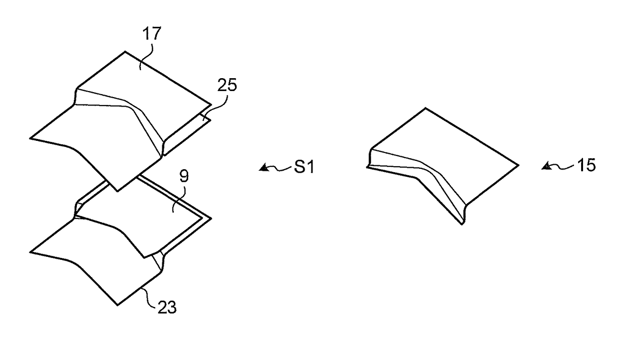
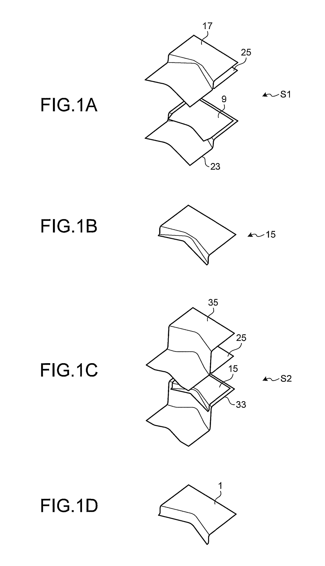
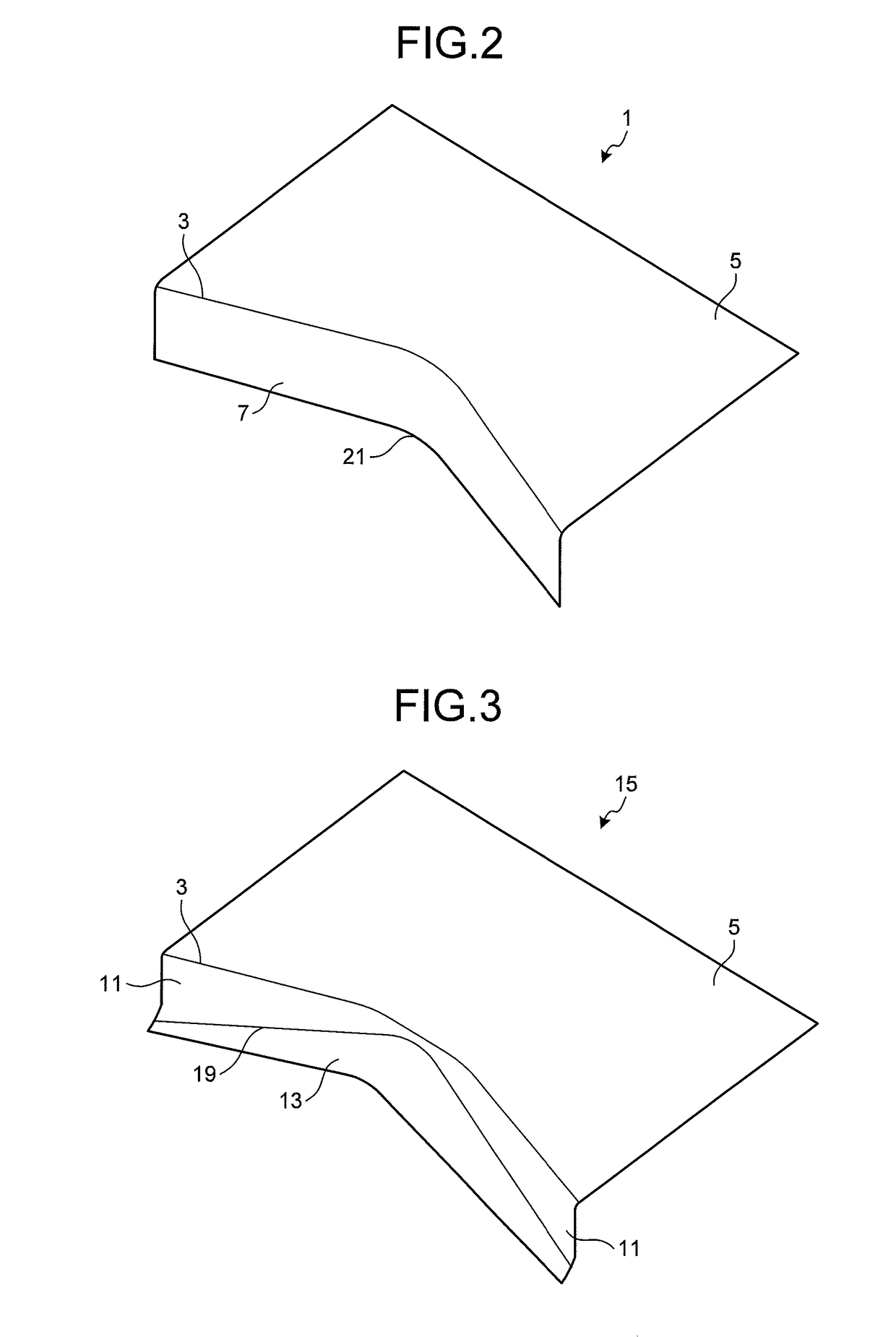
A press forming method of press forming a formed part including a top portion having a concave outer edge with a part of the outer edge being concave inwards and a flange portion subjected to bending forming along the concave outer edge of the top portion includes: a first forming step of forming a preformed shape part including, in a part where the flange portion is formed in a blank material, a vertical wall portion that becomes a part of the flange portion and a mountain shaped portion that is bent outwards from the vertical wall portion and is convex towards the top portion; and a second forming step of forming the flange portion by performing bending forming on a part including the mountain shaped portion of the preformed shape part formed at the first forming step along a bending line that is a boundary from the vertical wall portion.

Description

FIELD[0001]The present invention relates to a press forming method of forming a stretch flange by press forming a metal sheet.BACKGROUND[0002]When a flange portion is formed by press forming a metal sheet between tools of press forming, stretch deformation (a stretch flange) may occur by a bent end portion of the flange portion of the metal sheet receiving a tensile force. Such forming is called “stretch flange forming”. In stretch flange forming, if the stretch deformation exceeds the deformation limit of the metal sheet, a crack is generated. This crack is called “stretch flange crack”. In particular, a stretch flange crack easily occurs in a formed part of a high-strength steel sheet, for example, a press formed part for an automobile. If a stretch flange crack is generated, a prescribed part shape may not be obtained.[0003]As a method of avoiding such a stretch flange crack, for example, in Patent Literature 1, a method of suppressing generation of a stretch flange crack by impr...

Claims


Application Information

Patent Timeline
IPC IPC(8): B21D19/08B21D22/26B21D25/00B21D5/04
CPCB21D19/08B21D25/00B21D22/26B21D5/04
Inventor URABE, MASAKI
Owner JFE STEEL CORP
Learn More