
Reciprocating integral linear engine compressor

a linear engine and compressor technology, applied in the direction of positive displacement liquid engine, piston pump, free piston pump, etc., can solve the problems of reducing the efficiency and reliability and reducing the efficiency of the compressor cylinder

Active Publication Date: 2018-05-01
SOUTHWEST RES INST
View PDF2 Cites 2 Cited by
  • Summary
  • Abstract
  • Description
  • Claims
  • Application Information

AI Technical Summary

Problems solved by technology

Conventional reciprocating compressors, especially the large compressors used for natural gas pipelines, have a number of limitations in regard to emissions, efficiency and reliability.
However, the higher speeds create higher gas velocities in the compressor cylinders, which results in lower compressor cylinder efficiencies.

Method used


Image

  • Reciprocating integral linear engine compressor
  • Reciprocating integral linear engine compressor
  • Reciprocating integral linear engine compressor

Examples


Embodiment Construction

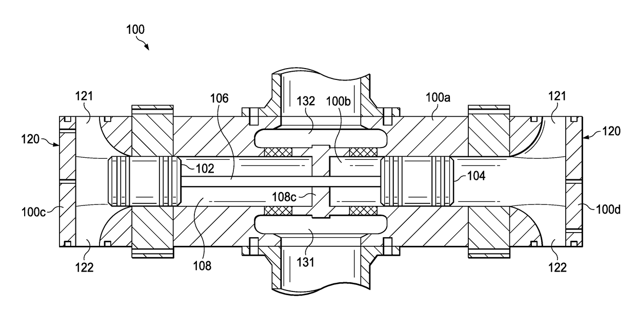
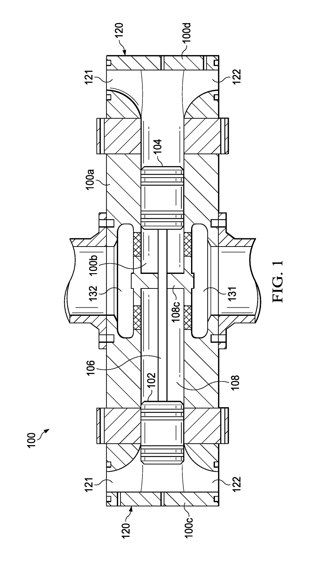
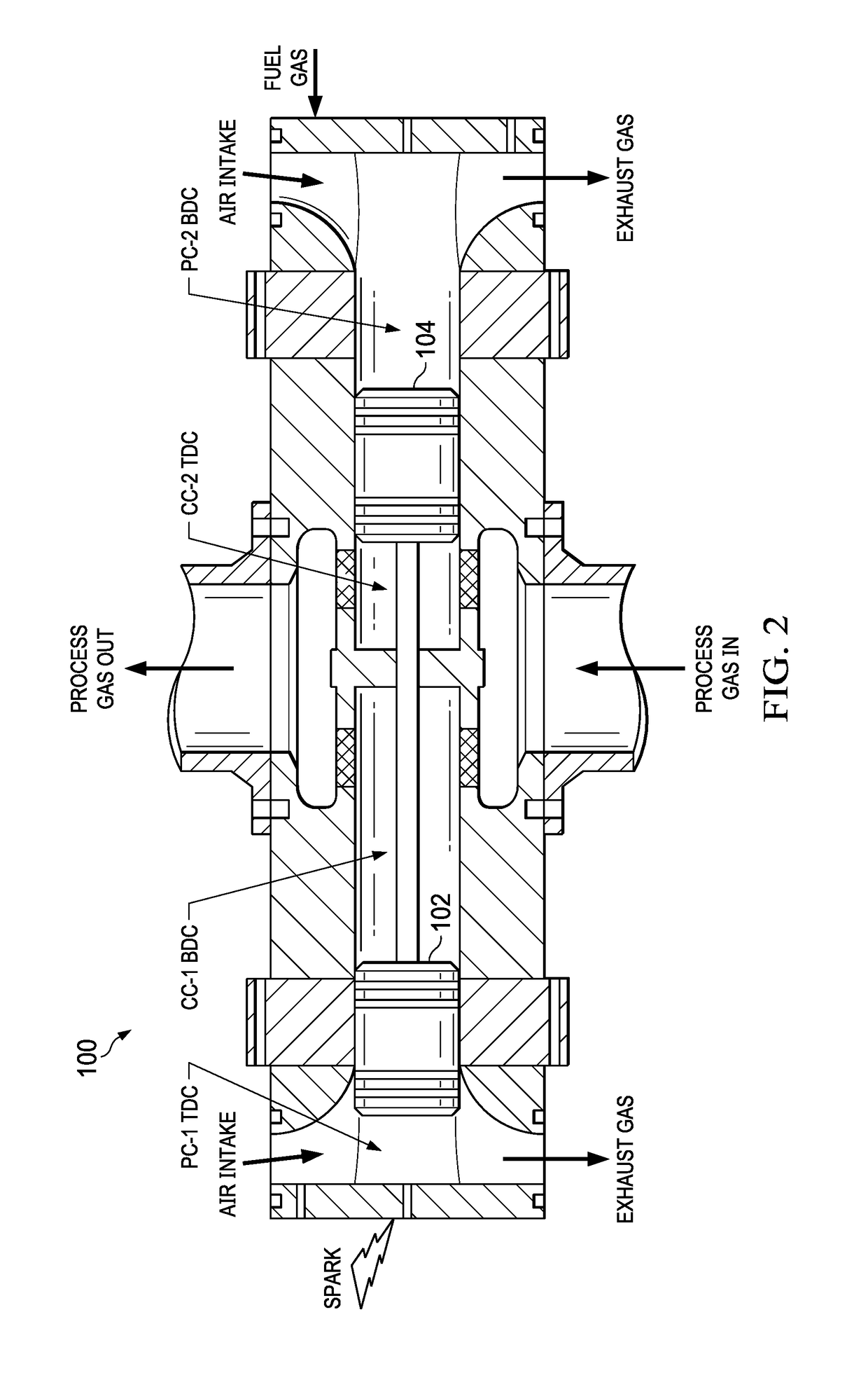
[0011]The following description is directed to a multi-cylinder unit for a reciprocating compressor. As explained below, a single housing with one bore contains two reciprocating pistons, but defines four chambers. Two outer chambers are each served by an outer end of a piston, and two inner chambers are each served by an inner end of a piston. The pistons are connected in the mid portion of the bore with a piston rod, which does not use a crankshaft.

[0012]With the above described configuration, the two outer chambers, the two inner chambers, and the two pistons define four cylinders. Two outer cylinders are power cylinders and two inner cylinders are compression cylinders.

[0013]For purposes of this description, the above described configuration is referred to as a “multi-cylinder compressor”. It should be understood that a number of these compressors may be used together as “compressor units” to form a larger compressor machine.

[0014]FIG. 1 illustrates the multi-cylinder compressor...


PUM


Abstract

A reciprocating compressor. A hollow cylinder tube contains a piston assembly having two pistons connected by a piston rod. At each end of the cylinder tube is an outer chamber between an end plate and an outer end of the proximate piston. These two outer chambers and the outer ends of the pistons define a power cylinder at each end of the cylinder tube. In the mid-portion of the cylinder tube, a center divider is situated between the pistons and has an aperture that allows the piston rod to reciprocate through it. The two inner chambers formed thereby and the inner ends of the pistons define two compression cylinders in the mid-portion of the cylinder tube. The two compression chambers share a suction manifold and a discharge manifold, but have independently operating suction and discharge valves.

Description

TECHNICAL FIELD OF THE INVENTION[0001]This invention relates to reciprocating compressors, and more particularly to cylinder configurations for such compressors.BACKGROUND OF THE INVENTION[0002]A reciprocating compressor is a type of positive-displacement compressor, and uses the movement of a piston within a cylinder to move gas from one pressure level to a higher pressure level. Intake gas enters a suction manifold, then flows into a compressor cylinder where it is compressed by a piston driven in a reciprocating motion via a crankshaft. The gas is then discharged via a discharge manifold.[0003]Examples of applications of reciprocating compressors are for oil refineries, gas pipelines, chemical plants, natural gas processing plants and refrigeration plants. For these large compressors, groups of cylinders are operated in parallel.[0004]Conventional reciprocating compressors, especially the large compressors used for natural gas pipelines, have a number of limitations in regard to ...

Claims


Application Information

Patent Timeline
Patent Type & Authority Patents(United States)
IPC IPC(8): F02B71/00F02B33/02F02B23/08F04B27/12F04B39/12F04B39/10F04B39/00F04B35/00F02B75/18F02B25/26F02D23/00
CPCF04B35/002F02B23/08F02B25/26F02B33/02F04B39/12F04B27/12F04B39/0022F04B39/10F02D23/005F04B27/005F04B31/00Y02T10/12
Inventor DEFFENBAUGH, DANNY M.
Owner SOUTHWEST RES INST
Learn More