
Network monitoring method using phantom nodes

a network monitoring and phantom node technology, applied in the field of communication networks, can solve the problems of alarming rate and size increase of communication networks

Active Publication Date: 2018-05-01
THE UNITED STATES OF AMERICA AS REPRESENTED BY THE SECRETARY OF THE NAVY
View PDF14 Cites 19 Cited by
  • Summary
  • Abstract
  • Description
  • Claims
  • Application Information

AI Technical Summary

Benefits of technology

The patent describes a method for managing network traffic in a Software-Defined Network (SDN) in the event of congestion or failure of certain devices. The method involves identifying underutilized devices in the network, determining congested devices, and setting a congestion threshold. The controller then routes traffic from the congested devices to the underutilized devices to mitigate the network congestion. The technical effect of this patent is improved network performance and reduced network congestion.

Problems solved by technology

Communication networks continue to grow in size and complexity at an alarming rate.
The adverse condition may be any of a network congestion state, a failed link, and a failed forwarding device in the SDN.

Method used


Image

  • Network monitoring method using phantom nodes
  • Network monitoring method using phantom nodes
  • Network monitoring method using phantom nodes

Examples


Embodiment Construction

[0048]The embodiments herein and the various features and advantageous details thereof are explained more fully with reference to the non-limiting embodiments that are illustrated in the accompanying drawings and detailed in the following description. Descriptions of well-known components and processing techniques are omitted so as to not unnecessarily obscure the embodiments herein. The examples used herein are intended merely to facilitate an understanding of ways in which the embodiments herein may be practiced and to further enable those of skill in the art to practice the embodiments herein. Accordingly, the examples should not be construed as limiting the scope of the embodiments herein.

[0049]The embodiments herein provide a network monitoring method using phantom nodes. Referring now to the drawings, and more particularly to FIGS. 1 through 32, where similar reference characters denote corresponding features for their specific figure, or may denote corresponding features cons...


PUM


Abstract

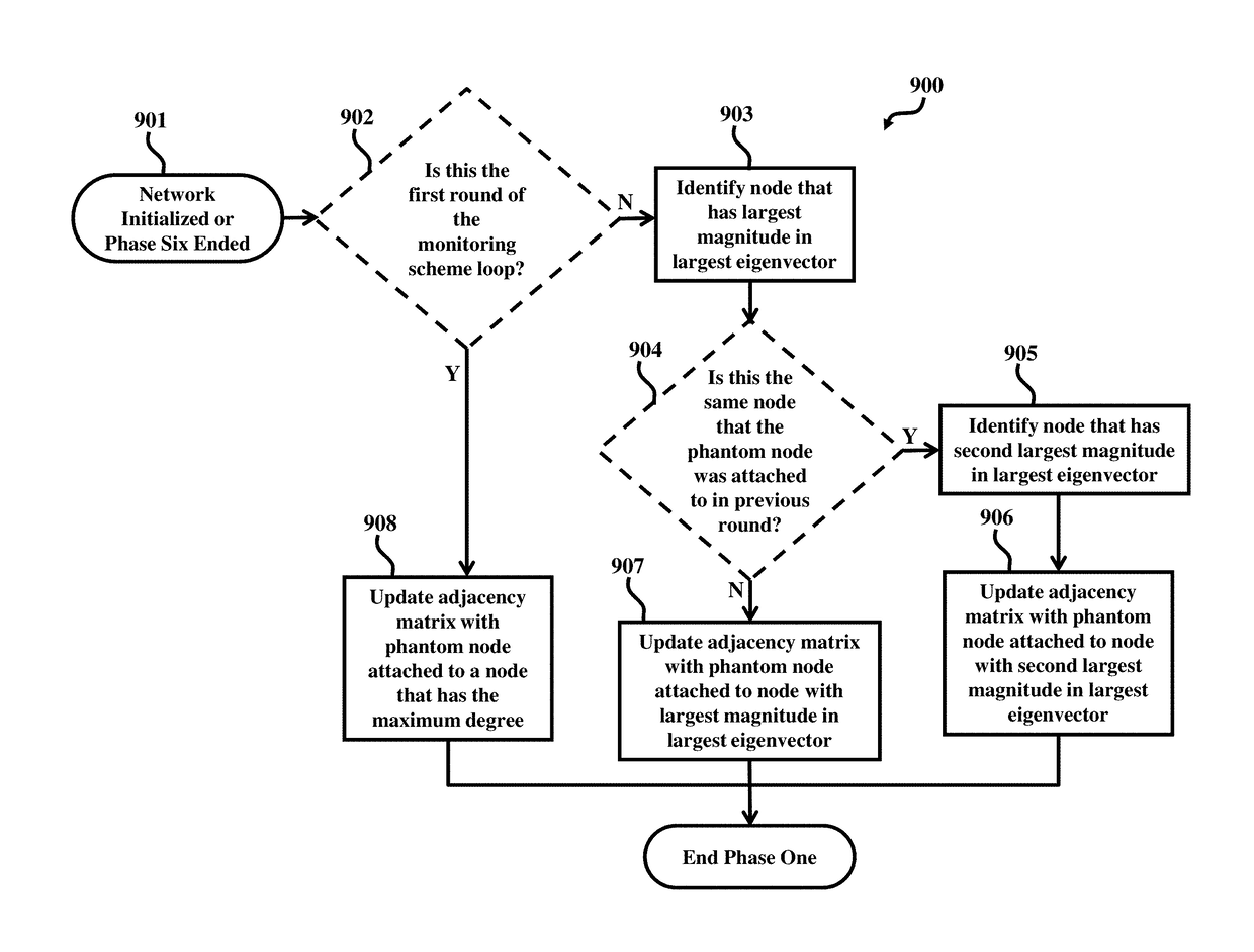
Determining flow rules in a software defined network (SDN) of a plurality of forwarding devices includes determining, by a controller device, a network adjacency matrix of the SDN, wherein the network adjacency matrix represents a topology of the SDN; placing, by the controller device, a phantom node in the network adjacency matrix, wherein the phantom node does not physically exist within the topology of the SDN and the phantom node is attached to a first node with maximum degree in the network adjacency matrix to create a phantom adjacency matrix, wherein the first node corresponds to a first forwarding device in the SDN; and determining, by the controller device, an adverse condition in the SDN using the phantom node, wherein the controller device is separate from the plurality of forwarding devices.

Description

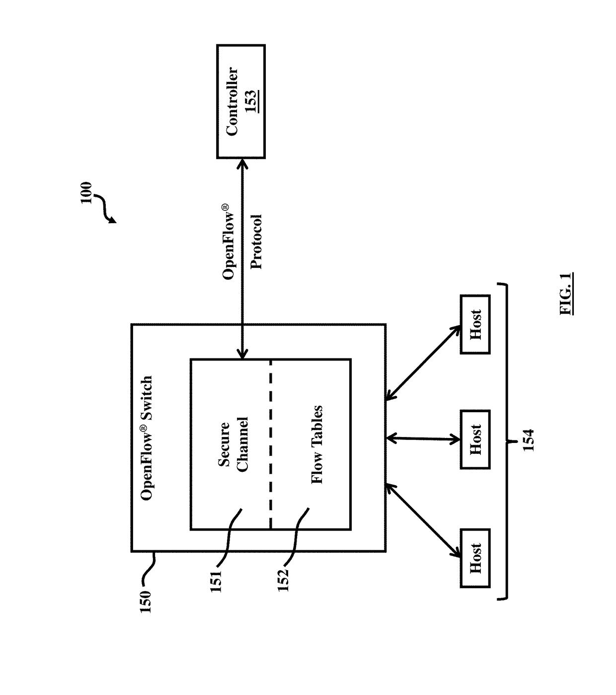
CROSS-REFERENCE TO RELATED APPLICATIONS[0001]This application claims priority to U.S. Provisional Patent Application No. 62 / 064,361 filed on Oct. 15, 2014, the complete disclosure of which, in its entirety, is herein incorporated by reference.BACKGROUNDTechnical Field[0002]The embodiments herein relate to communication network, and more particularly to flow control in communication networks.Description of the Related Art[0003]Communication networks continue to grow in size and complexity at an alarming rate. A recent development for communication networks is the emergence of software-defined networking (SDN). A SDN is designed to have a programmable controller that provides flow level routing instruction to the network forwarding elements. This design separates the control plane from the data plane causing switches to rely on the centralized controller for control-plane functionalities. The controller provides these functionalities to the switches through an open interface called th...

Claims


Application Information

Patent Timeline
IPC IPC(8): H04L12/24H04L12/939H04L12/801H04L12/803H04L12/703H04L45/28
CPCH04L41/0659H04L45/28H04L49/557H04L47/11H04L47/125H04L41/142H04L43/0888H04L41/40H04L41/122H04L43/20H04L41/12
Inventor JOHNSON, JAMIE LYNNPARKER, THOMASTUMMALA, MURALIMCEACHEN, JOHN C.
Owner THE UNITED STATES OF AMERICA AS REPRESENTED BY THE SECRETARY OF THE NAVY
Learn More