

Bead ring winding device
a technology of winding device and beads, which is applied in the direction of wire rings, tyres, domestic applications, etc., can solve the problems of difficult to accurately move the former, impede the stable feeding of wires to the circumference of the replacement former, and the overall device including the former is very heavy. , to achieve the effect of easy and accurate movemen
Inactive Publication Date: 2018-05-15
FUJISEIKO +1
View PDF19 Cites 0 Cited by
- Summary
- Abstract
- Description
- Claims
- Application Information
AI Technical Summary
Benefits of technology
The present invention makes it easy and accurate to move a replacement former onto a different diameter shaft. This ensures that the replacement former is positioned correctly.
Problems solved by technology
This hinders stable feeding of the wire to the circumference of the replacement former.
However, the overall device including the former is very heavy.
Thus, it would be burdensome and difficult to accurately move the former to the predetermined position.
Method used
View moreImage
Smart ImageViewing Examples

Examples
modified examples
[0045]The present embodiment may be modified as described below.
[0046]In the above embodiment, the position of the upper end of the former 18 may be set based on only the detection of the detector 23.
[0047]The biasing device 26 may be omitted from the above embodiment.
Login to View More PUM
| Property | Measurement | Unit |
|---|---|---|
| circumference | aaaaa | aaaaa |
| diameter | aaaaa | aaaaa |
| height | aaaaa | aaaaa |
Abstract
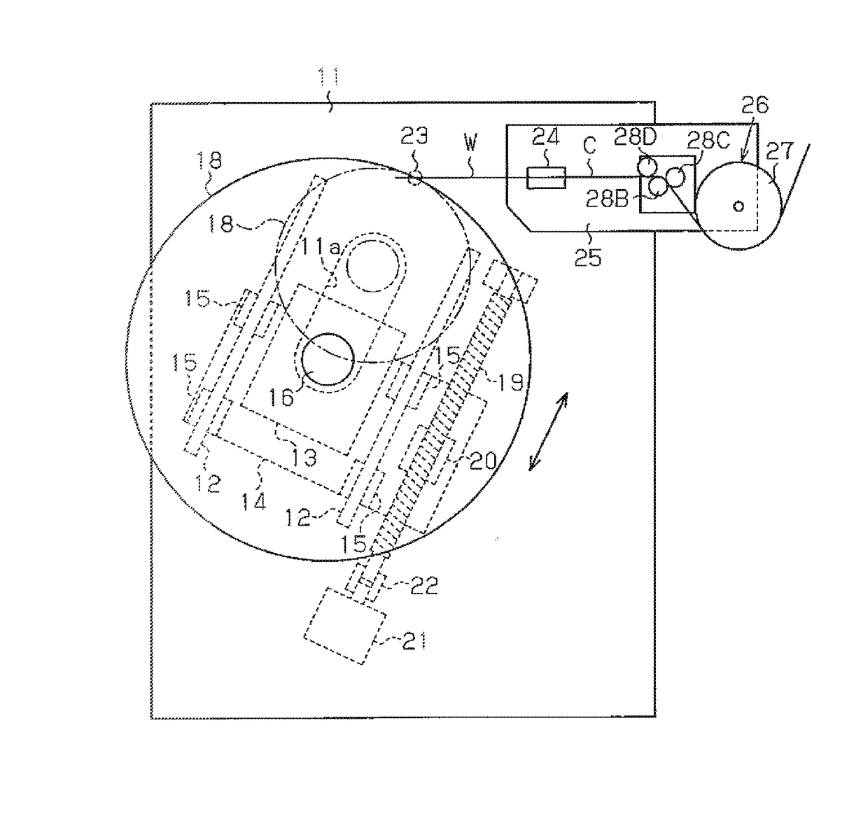
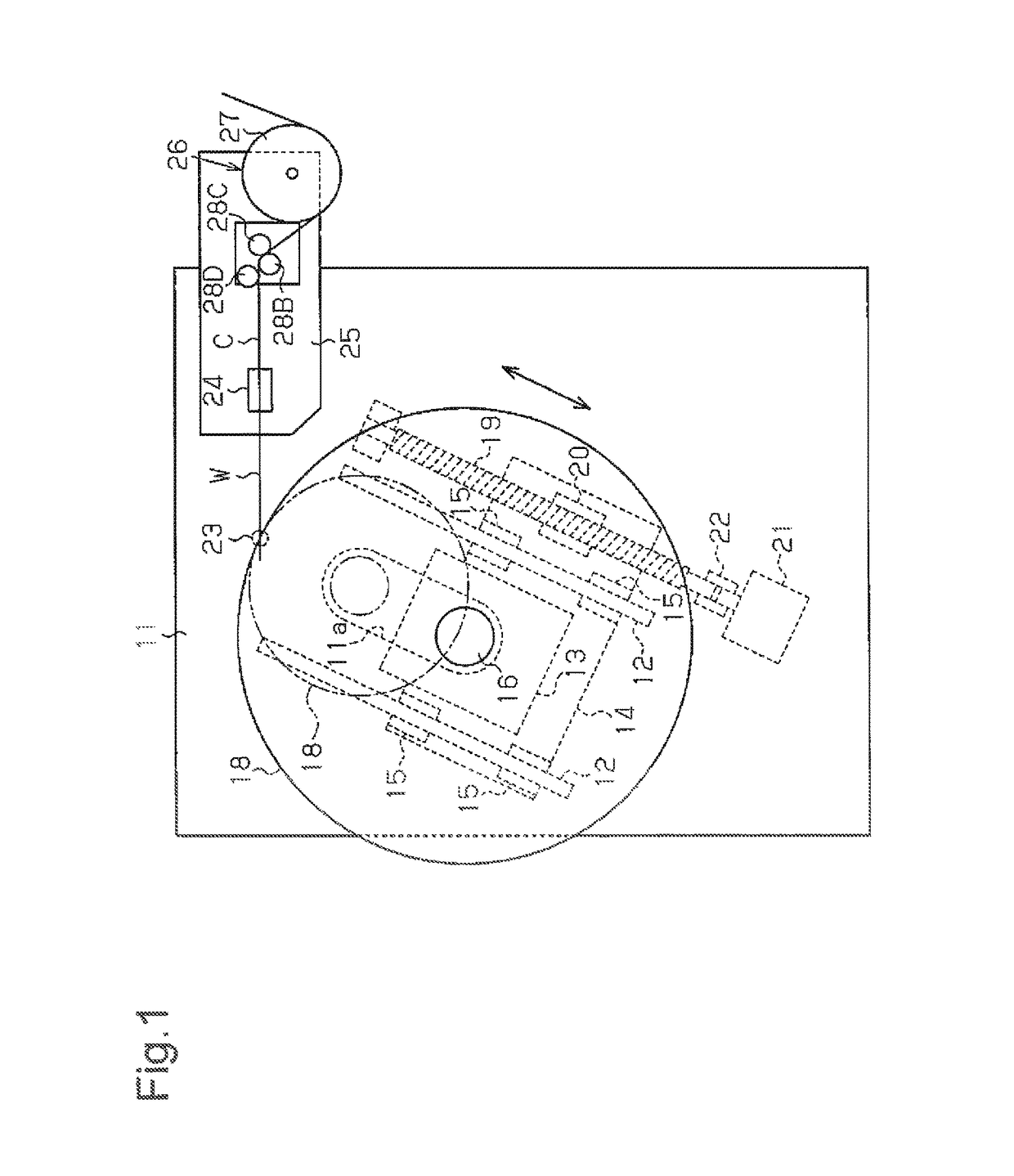
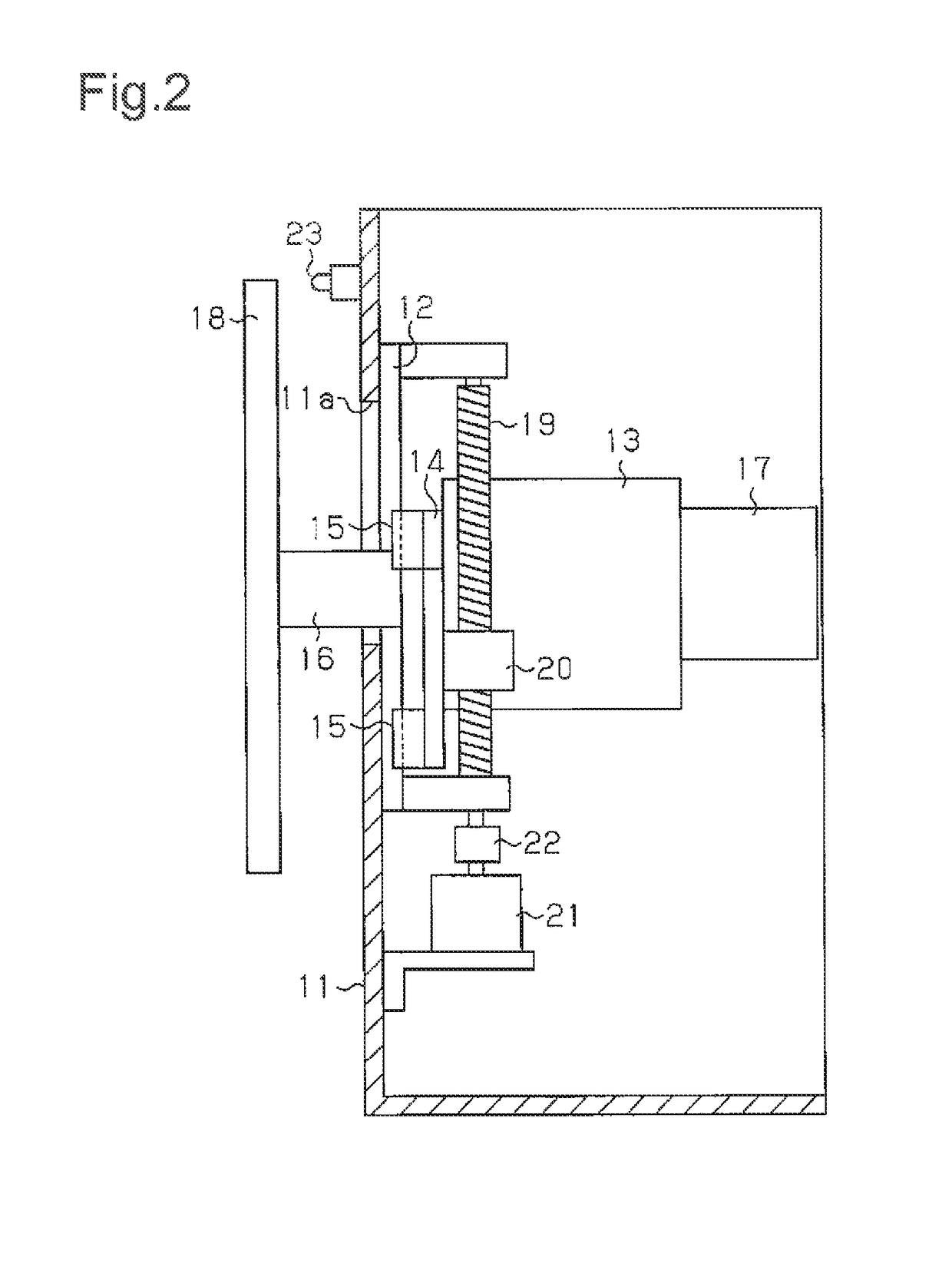
A bead ring winding device forms a bead ring by winding a wire fed to the circumference of a former, which is coupled to, in a removable manner, and supported by a rotation shaft. The bead ring winding device includes a guide and a driving member. The guide guides a bearing so that the bearing can be lifted and lowered. The bearing supports the rotation shaft. The driving member lifts and lowers the bearing along the guide. When the former is replaced with another former of a different diameter, the bearing is lifted or lowered with the driving member so that the upper end of the former is arranged at a fixed position.
Description
RELATED APPLICATIONS[0001]The present invention is a U.S. National Stage under 35 USC 371 patent application, claiming priority to Serial No. PCT / JP2012 / 061207, filed on 26 Apr. 2012; the entirety of which is incorporated herein by reference.TECHNICAL FIELD[0002]The present invention relates to a bead ring winding device that winds a wire around the circumference of a former to form a bead ring.BACKGROUND ART[0003]A typical bead ring winding device includes a wire feeding unit located at a height corresponding to the upper end of a former, which is supported by a rotation shaft. Wire is fed from the feeding unit to the circumference of the former as the former rotates to wind the wire and form a bead ring. Conventionally, in a bead ring winding device of such a structure, when changing the winding diameter of the bead ring that is to be formed, the former is removed from the rotation shaft and replaced with another former having a diameter conforming to that bead ring winding diamet...
Claims
Login to View More Application Information
Patent Timeline
 Patent Type & AuthorityPatents(United States)
IPC IPC(8): B21F37/00B29D30/48
CPCB21F37/00B29D30/48B29D2030/487
InventorNOMURA, SHIGEAKI
OwnerFUJISEIKO