
A lamp holder automatic assembly machine

An assembly machine and assembly mechanism technology, applied in metal processing equipment, metal processing, manufacturing tools, etc., can solve problems such as labor-intensive, failure to meet assembly standards, and looseness of two parts, and achieve high efficiency, convenient movement and precise effect

Active Publication Date: 2021-03-09
广东蓝云照明工程有限公司
View PDF8 Cites 0 Cited by
  • Summary
  • Abstract
  • Description
  • Claims
  • Application Information

AI Technical Summary

Problems solved by technology

[0002] The E17 lamp holder is composed of a lamp housing and a base. One end of the base is provided with a threaded connector, which is just threaded with the inner thread of the lamp housing. The outer end of the lamp housing is also connected with a threaded joint. The traditional assembly method is mostly held by two hands. The base and the lamp housing are assembled. This method not only consumes manpower, but after assembling several lamp holders, due to physical exertion, the assembly standard may not be met, which may cause looseness between the two parts. Therefore, the present invention proposes a lamp holder automatic assembly machine

Method used

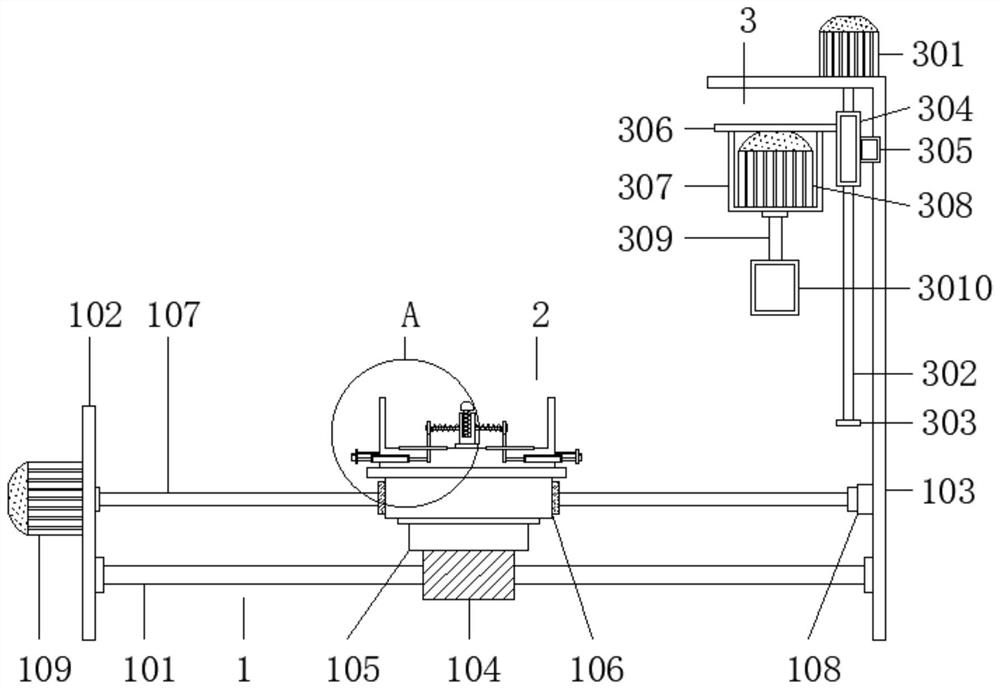

Image

  • A lamp holder automatic assembly machine
  • A lamp holder automatic assembly machine
  • A lamp holder automatic assembly machine

Examples


Embodiment Construction

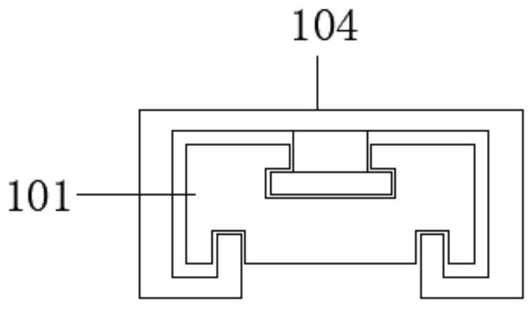
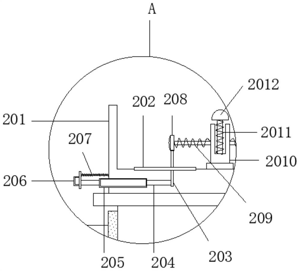
[0020] Such as Figure 1-3 As shown, this specific embodiment adopts the following technical solutions: an automatic lamp holder assembly machine, including a moving mechanism 1, a clamping mechanism 2 is arranged on the moving mechanism 1, and the moving mechanism 1 on one side of the clamping mechanism 2 An assembly mechanism 3 is arranged on it, and the moving mechanism 1 includes a slide rail 101, a left support plate 102 is fixedly connected to one side of the slide rail 101, and a left support plate 102 is fixedly connected to the other side of the slide rail 101 relative to the left support plate 102. There is a support frame 103, a slide block 104 is slidably connected to the slide rail 101, a No. 1 connecting plate 105 is fixedly connected above the slide block 104, and the No. 1 connecting plate 105 is slidably connected to the slide rail 101 through the slide block 104, A No. 1 movable threaded sleeve 106 is fixedly connected to the other side of the No. 1 connectin...


PUM


Abstract

The invention discloses an automatic lamp holder assembly machine, which includes a moving mechanism, a clamping mechanism is arranged on the moving mechanism, and an assembly mechanism is arranged on the moving mechanism on one side of the clamping mechanism. , use the lamp housing fixing groove to fix one end of the lamp housing of the E17 lamp holder on the lamp housing fixing groove, and then drive the lamp housing fixing groove to move down through the No. 2 movable threaded sleeve, so that the upper lamp housing and the clamping mechanism Then turn on the No. 3 servo motor to rotate the fixing groove of the lamp housing, so that the lamp housing and the lamp holder are connected through the threads on the inner wall and the outer wall. After the connection is completed, turn on the No. Start the No. 2 servo motor, the fixing groove of the lamp housing will move up while rotating in the opposite direction, so that the fixing groove of the lamp housing will be separated from the lamp housing, and then the finished product on the clamping mechanism will be removed. This design, compared with the traditional manual assembly ,higher efficiency.

Description

Technical field: [0001] The invention belongs to the technical field of mechanical equipment, in particular to an automatic lamp holder assembly machine. Background technique: [0002] The E17 lamp holder is composed of a lamp housing and a base. One end of the base is provided with a threaded connector, which is just threaded with the inner thread of the lamp housing. The outer end of the lamp housing is also connected with a threaded joint. The traditional assembly method is mostly held by two hands. The base and the lamp housing are assembled. This method not only consumes manpower, but after assembling several lamp holders, due to physical exertion, the assembly standard may not be met, which may cause looseness between the two parts. Therefore, the present invention proposes an automatic assembly machine for lamp holders. Invention content: [0003] The object of the present invention is to provide an automatic assembly machine for lamp holders in order to solve the ...

Claims


Application Information

Patent Timeline
Patent Type & Authority Patents(China)
IPC IPC(8): B23P19/04
CPCB23P19/006B23P19/04
Inventor 任新庄
Owner 广东蓝云照明工程有限公司
Learn More