Terminal block with a terminal cover

a terminal block and terminal cover technology, applied in the direction of electrical equipment, connection, coupling device connection, etc., can solve the problems of terminal cover damage or come off, terminal cover is difficult to detach,

Active Publication Date: 2018-05-15
TDK CORPARATION
View PDF10 Cites 0 Cited by
  • Summary
  • Abstract
  • Description
  • Claims
  • Application Information

AI Technical Summary

Benefits of technology

[0034]According to the invention set forth in the foregoing (13), the first direction and the second direction are substantially perpendicular. This produces an effect of providing a terminal block to which load lines can be connected in two mutually-perpendicular directions.
[0035]According to the present invention, there is prov

Problems solved by technology

If a plate-like terminal cover like the one shown in FIG. 9B is used for such terminal portions, the load lines can come into contact with the terminal cover, and the terminal cover can be damaged

Method used


Image

  • Terminal block with a terminal cover
  • Terminal block with a terminal cover
  • Terminal block with a terminal cover

Examples


Embodiment Construction

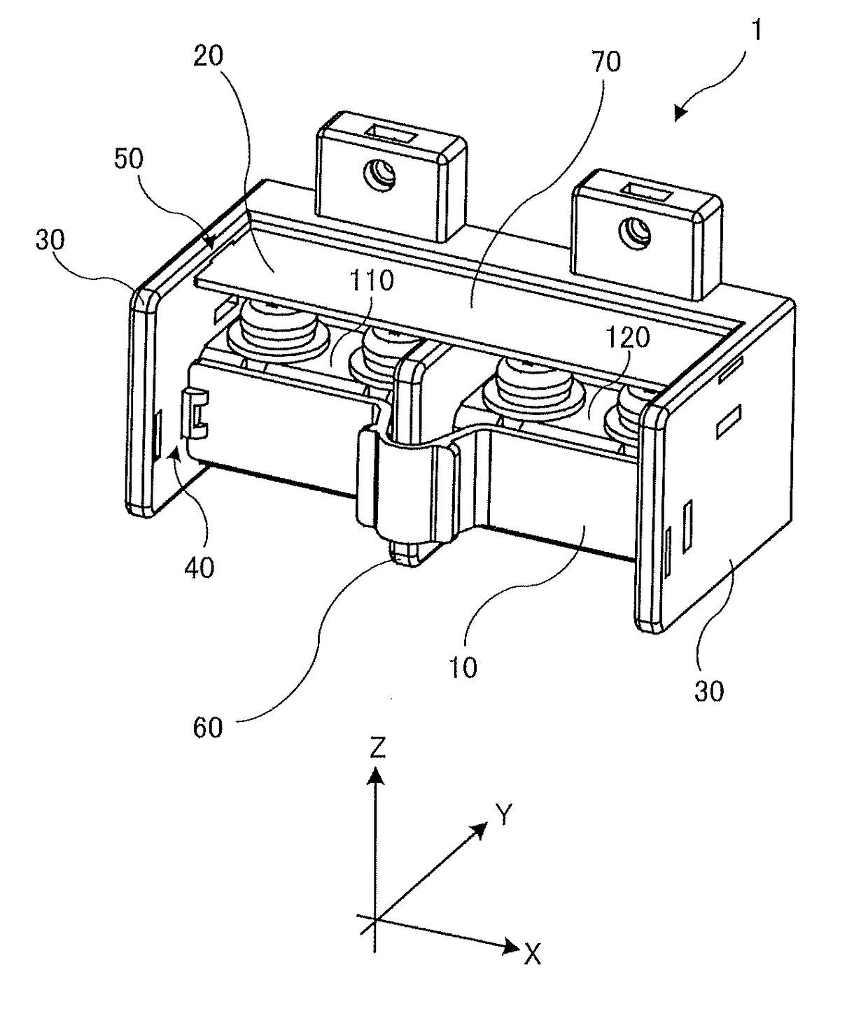
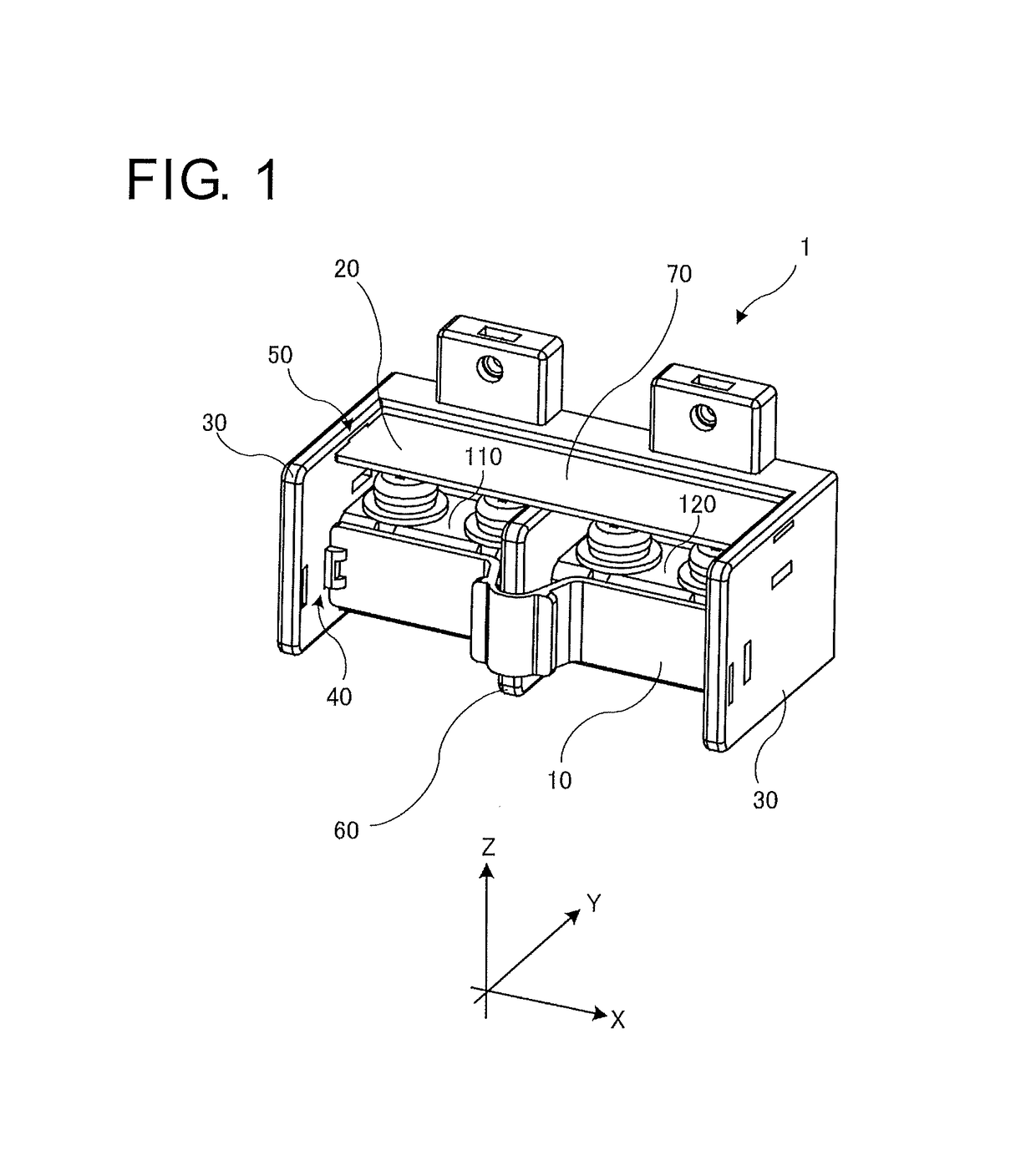
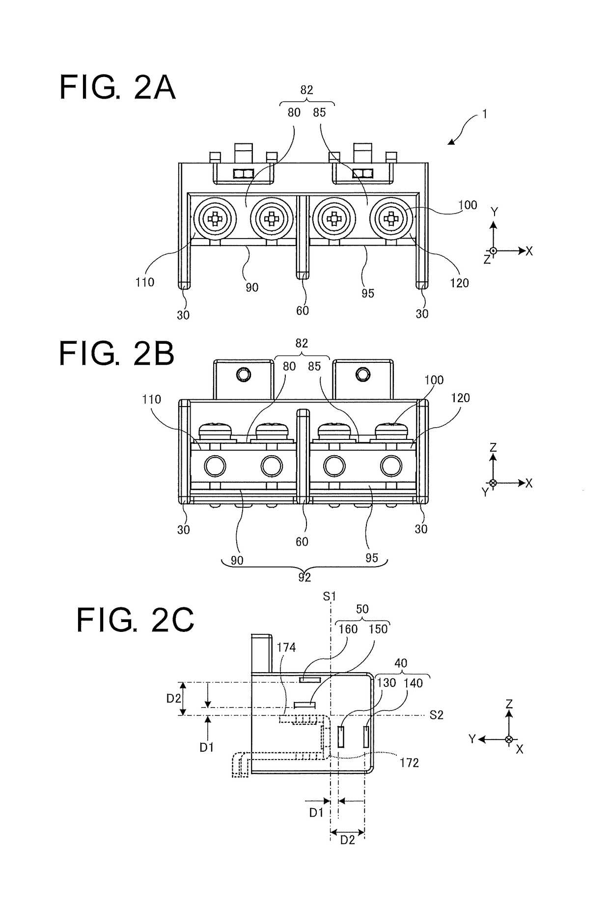
[0045]An embodiment of the present invention will be described below with reference to the accompanying drawings. FIGS. 1 to 8 show an example of embodiment of the present invention. In the diagrams, portions denoted by the same reference numerals represent the same components. In the diagrams, some of the configurations are omitted as appropriate for simplification. Members may be exaggerated in size, shape, thickness, and the like if needed.

[0046]FIG. 1 shows a terminal block 1 according to the embodiment of the present invention. The terminal block 1 includes: a terminal block main body portion 70 that is made of an insulating material; a pair of side walls 30 that constitute part of the terminal block main body portion 70; a separator 60 that is erected between the pair of side walls 30 to be continuous with the terminal block main body portion 70; a first conductive plate 110 that is arranged between one of the side walls 30 and the separator 60; a second conductive plate 120 t...


PUM


Abstract

There is provided a terminal block to which load lines can be attached in multiple directions and which includes a terminal cover that makes terminal portions difficult for fingers to touch and is less likely to damage the load lines. The terminal block includes: a conductive plate including a first-direction connection portion that extends in a first direction and is capable of being connected with at least one wire, and a second-direction connection portion that is in electrical conduction with the first-direction connection portion, extends in a second direction different from the first direction, and is capable of being connected with at least one wire.

Description

BACKGROUND OF THE INVENTION[0001]1. Field of the Invention[0002]The present invention relates to a terminal block used for connecting inputs and outputs of electronic equipment.[0003]2. Description of the Related Art[0004]Terminal blocks for connecting inputs and outputs have conventionally been attached to electronic equipment such as a power supply apparatus. FIG. 9A shows a conventional terminal block 101. The terminal block 101 has a structure in which side walls 290 are erected on a base block made of an insulating material, and a plurality of terminal portions 310 are arranged between the side walls 290. In the structure, as shown in FIG. 9B, a plate-like terminal cover 300 further covers the tops of the terminals to prevent fingers and conductive parts from accidentally touching the terminal portions 310 or screws 100 (for example, see Japanese Patent Application Laid-Open No. 2000-113918.[0005]Another terminal block having a structure capable of selectively attaching load li...

Claims


Application Information

Patent Timeline
IPC IPC(8): H01R9/22H01R9/24H01R9/18H01R4/34
CPCH01R9/223H01R9/2416H01R9/18H01R4/34H01R9/24H01R13/447
Inventor KITATANI, KAZUHARU
Owner TDK CORPARATION
Why Eureka
Try Eureka