Container, and selectively formed shell, and tooling and associated method for providing same

a technology of can ends and metal containers, applied in the field of containers, can solve the problems of sacrificing the area of the end panel, developing unique solutions, and reducing the amount of metal required, and achieving the effect of achieving the desired strength

Active Publication Date: 2018-05-22
STOLLE MACHINERY CO LLC
View PDF49 Cites 8 Cited by
  • Summary
  • Abstract
  • Description
  • Claims
  • Application Information

AI Technical Summary

Benefits of technology

[0010]These needs and others are met by the disclosed concept, which is directed to a selectively formed shell, a container employing the selectively formed shell, and tooling and associated methods for making the shell. Among other benefits, the shell is selectively stretched and thinned to reduce the amount of metal required while maintaining the desired strength.
[0017]These needs and others are met by the disclosed concept, which is directed to a tooling including a force and / or pressure concentrating forming surface and / or a hybrid bias generating assembly. In an exemplary embodiment, the hybrid bias generating assembly is one of an active hybrid bias generating assembly or a selectable hybrid bias generating assembly, as defined below. It is understood that, in the known art, to increase the pressure acting on a shell, manufacturers simply increased the pressure acting on the tooling. This increase in pressure created a counter load that was applied to the press. As disclosed herein, concentrating the force / pressure on a forming surface allows for reduced counter loads to be applied to the press. An increase in the pressure surface area of the upper surface of the upper tool assembly and a reduction in the forming surface area that clamps the blanks solves the stated problem. In an exemplary embodiment, the concentrating forming surface allows for a ratio of the total bias pressure to the clamping pressure of between about 1:10 to 1:50, or between about 1:20 and 1:40, or about 1:30. That is, a total bias pressure is applied to a pressure surface and the resulting pressure at the clamping surface is between about 10 to 50, or between about 20 and 40, or about 30 times greater. Such ratios of total bias pressure to the clamping pressure allows for a reduction in the loading condition on the tooling and / or press and therefore solves the stated problem. Further, the use of a hybrid bias generating assembly prevents an excessive amount of uneven thinning and therefore solves the stated problem.

Problems solved by technology

However, as less material (e.g., thinner gauge) is used, problems arise that require the development of unique solutions.
However, among other disadvantages associated with the formation of can ends from relatively thin gauge material, is the tendency of the can end to wrinkle, for example, during forming of the shell.
Prior proposals for reducing the volume of metal used reduce the blank size for the can end, but sacrifice the area of the end panel.
This undesirably limits the available space, for example, for the scoreline, the severable panel and / or the pull tab.
Further, the selective thinning may result in excessively uneven thinning.
That is, while some unevenness in the thinning is acceptable, excessive uneven thinning is not desirable.

Method used


Image

  • Container, and selectively formed shell, and tooling and associated method for providing same
  • Container, and selectively formed shell, and tooling and associated method for providing same
  • Container, and selectively formed shell, and tooling and associated method for providing same

Examples


Embodiment Construction

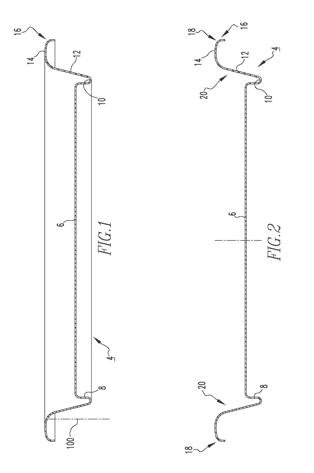
[0033]For purposes of illustration, embodiments of the disclosed concept will be described as applied to shells for a can end known in the industry as a “B64” end, although it will become apparent that they could also be employed to suitably selectively stretch and thin predetermined portions or areas of any known or suitable alternative type (e.g., without limitation, beverage / beer can ends; food can ends) and / or configuration other than B64 ends.

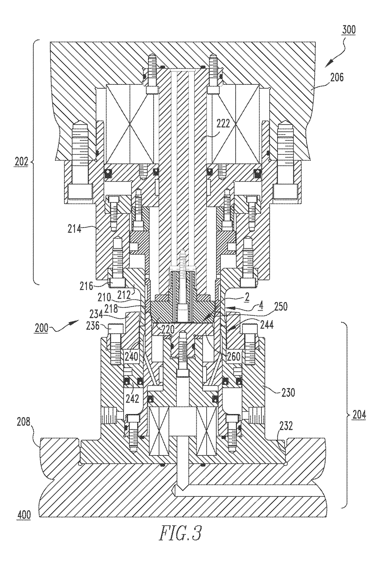
[0034]It will be appreciated that the specific elements illustrated in the figures herein and described in the following specification are simply exemplary embodiments of the disclosed concept, which are provided as non-limiting examples solely for the purpose of illustration. Therefore, specific dimensions, orientations, assembly, number of components used, embodiment configurations and other physical characteristics related to the embodiments disclosed herein are not to be considered limiting on the scope of the disclosed concept.

[0035]D...


PUM

PropertyMeasurementUnit
thicknessaaaaaaaaaa
thicknessaaaaaaaaaa
pressureaaaaaaaaaa

Abstract

A shell, a container employing the shell, and tooling and associated methods for forming the shell are provided. The shell includes a center panel, a circumferential chuck wall, an annular countersink between the center panel and the circumferential chuck wall, and a curl extending radially outwardly from the chuck wall. The material of at least one predetermined portion of the shell is selectively stretched relative to at least one other portion of the shell, thereby providing a corresponding thinned portion. The tooling includes a pressure concentrating forming surface.

Description

CROSS-REFERENCE TO RELATED APPLICATION[0001]This application is continuation-in-part application of U.S. patent application Ser. No. 13 / 894,017, filed May 14, 2013, which application claims the benefit of U.S. Provisional Patent Application Ser. No. 61 / 648,698, filed May 18, 2012, entitled “CONTAINER, AND SELECTIVELY FORMED SHELL, AND TOOLING AND ASSOCIATED METHOD FOR PROVIDING SAME.”BACKGROUND[0002]Field[0003]The disclosed concept relates generally to containers and, more particularly, to can ends or shells for metal containers such as, for example, beer or beverage cans, as well as food cans. The disclosed concept also relates to methods and tooling for selectively forming a can end or shell to reduce the amount of material used therein.[0004]Background Information[0005]Metallic containers (e.g., cans) for holding products such as, for example, food and beverages, are typically provided with an easy open can end on which a pull tab is attached (e.g., without limitation, riveted) t...

Claims


Application Information

Patent Timeline
Patent Type & Authority Patents(United States)
IPC IPC(8): B21D37/10B21D22/24B21D51/38
CPCB21D37/10B21D51/38B21D22/24Y10T428/12389B21D22/22B21D24/04B21D51/44
Inventor CARSTENS, AARON E.MCCLUNG, JAMES A.RIPPLE, PAUL L.BUTCHER, GREGORY H.MCCARTY, PATRICK K.
Owner STOLLE MACHINERY CO LLC
Why Eureka
Try Eureka