Cable assembly for use with opto-electronic equipment enclosures

a technology of opto-electronic equipment and enclosures, applied in the direction of optics, fibre mechanical structures, instruments, etc., can solve the problems of no mechanism, no additional protection provided for fibers, no mechanism,

Inactive Publication Date: 2001-01-23
SIECOR A DELAWARE
View PDF28 Cites 193 Cited by
  • Summary
  • Abstract
  • Description
  • Claims
  • Application Information

AI Technical Summary

Problems solved by technology

There are several disadvantages associated with the current practices for installation, termination, and environmental sealing of fiber optic cables placed into cable television system electronic equipment enclosures.
No additional protection is provided for the fibers, no mechanism is provided to control core pistoning into the enclosure, and no mechanism is provided to block the migration of water from entering the electronic enclosure if the cable sheath is damaged behind the strain relief connector.
The current method is also labor intensive and costly to the cable television company.

Method used


Image

  • Cable assembly for use with opto-electronic equipment enclosures
  • Cable assembly for use with opto-electronic equipment enclosures
  • Cable assembly for use with opto-electronic equipment enclosures

Examples


Embodiment Construction

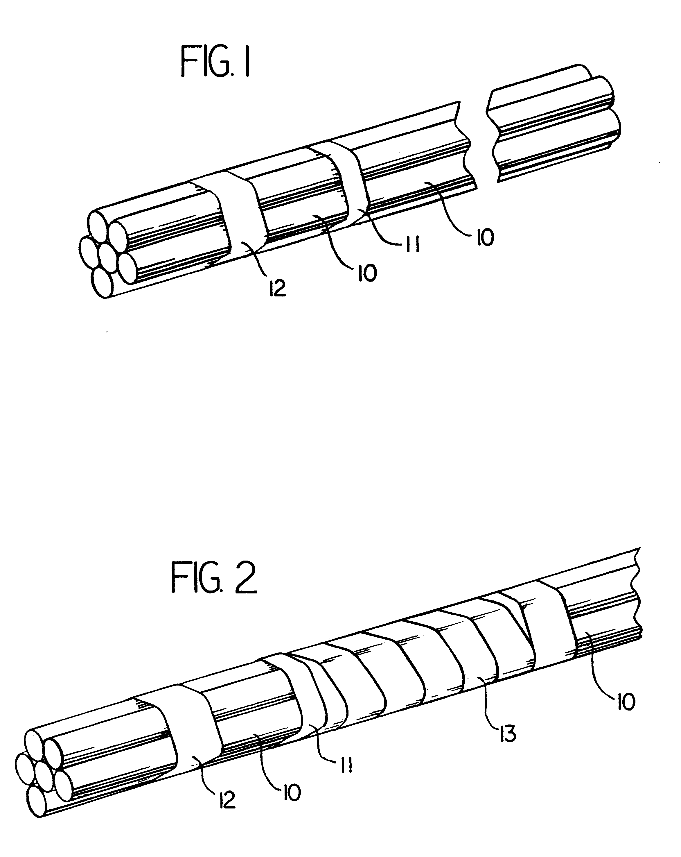
An array of flexible tubes 10 are bundled as shown in FIG. 1 by two strips 11, 12 of heat shrinkable material which are preferably 1 / 4 inch wide. Tubes 10 are preferably made of a lightweight, low friction, highly flexible plastic such as Teflon.RTM. plastic. Strips 11, 12 are placed 3 / 16th of an inch apart. Strip 12 is located around 1 / 4 inch from one end of tubes 10.

After strips 11, 12 have cooled, spiral wrap material 13 is placed over the bundle of tubes 10, with one edge over strip 11 and the remainder proceeding in the direction opposite strip 12.

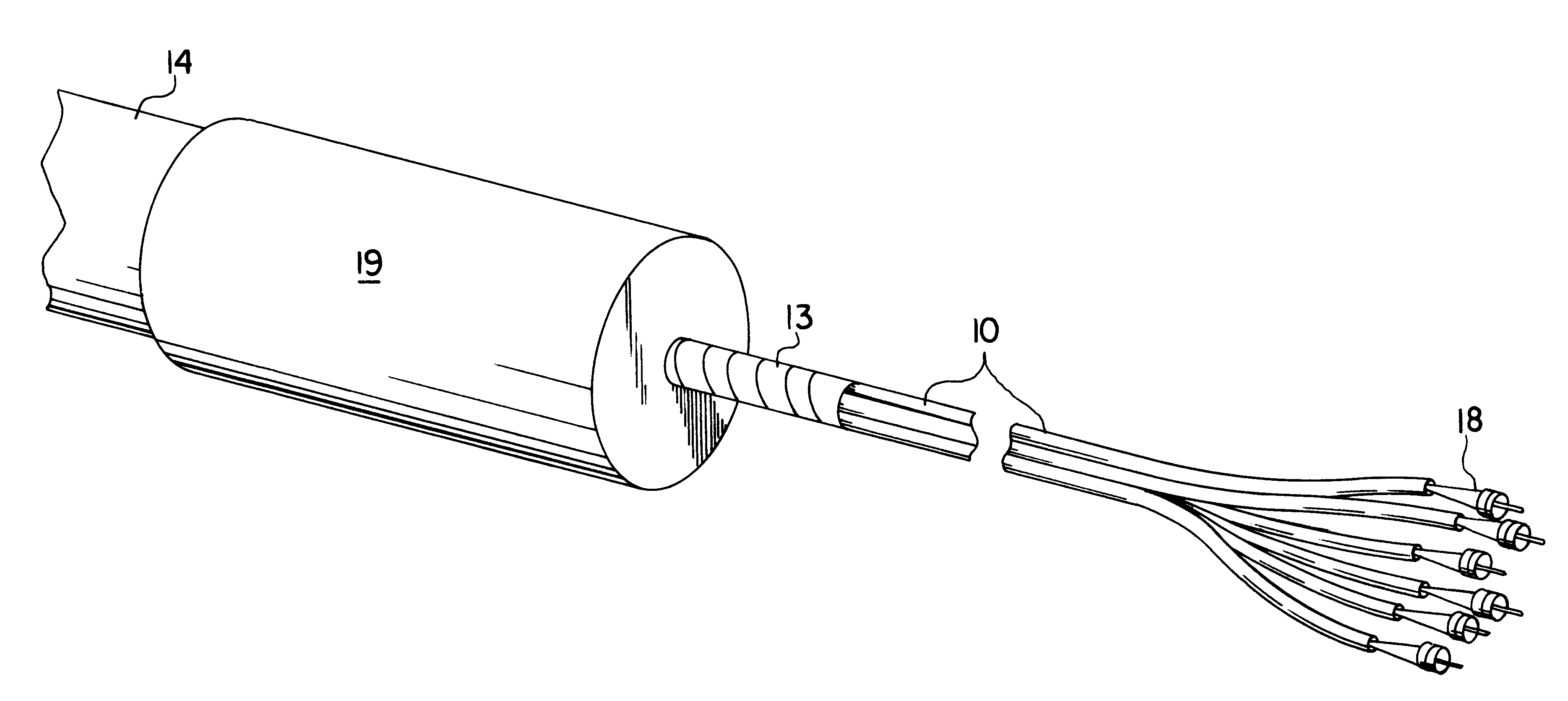
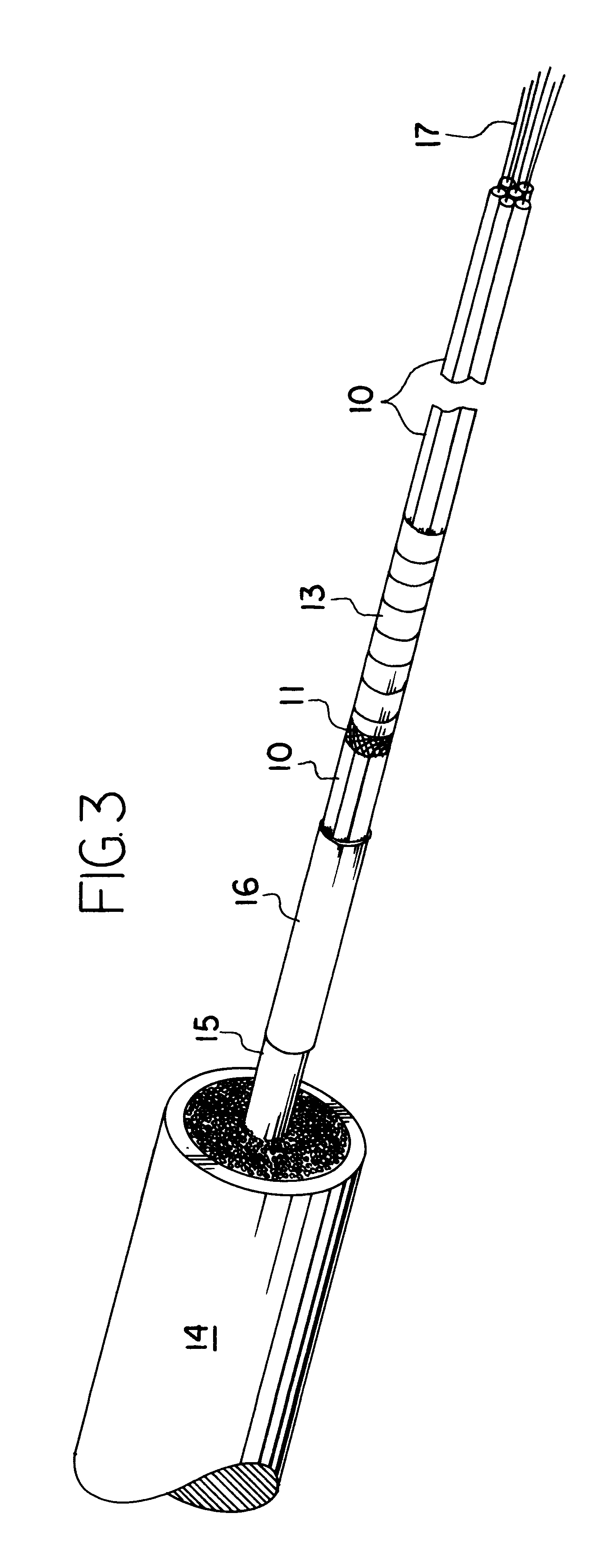
A light waveguide cable is then prepared as shown in FIG. 3. After one end of cable jacket 14 has been cut back, a buffer tube 15 including light waveguides 17 extends a short distance. Each fight waveguide 17 is threaded through a flexible tube 10, with an optical coupler 18 being placed on the distal end of each fight waveguide 17. As shown in FIG. 4, tubes 10 extend to meet the rear of couplers 18. A protective boot on each coupler...


PUM


Abstract

Light, flexible tubes are placed around optical fibers extending from the end of a cable jacket. A water impervious plug encases the end of the cable jacket and a portion of the flexible tubes. Couplers are attached to the light waveguide terminal ends and the optical couplers and the plug are placed in an opto-electronic equipment closure. The assembly is designed for use with cable television system aerial closures.

Description

BACKGROUND OF THE INVENTIONThe field of the invention is optical cable assembles.Background of the Invention. There are several disadvantages associated with the current practices for installation, termination, and environmental sealing of fiber optic cables placed into cable television system electronic equipment enclosures. A prior art practice is to strip back the end of a fiber optic cable and feed the exposed coated optical fibers into the fiber optic entry point of an electronic closure. A threaded connector on the cable is screwed into the entry port. The connector, after tightening, grips the fiber optic cable jacket for strain relief. The exposed fibers are then fusion spliced inside the enclosure. No additional protection is provided for the fibers, no mechanism is provided to control core pistoning into the enclosure, and no mechanism is provided to block the migration of water from entering the electronic enclosure if the cable sheath is damaged behind the strain relief ...

Claims


Application Information

Patent Timeline
Patent Type & Authority Patents(United States)
IPC IPC(8): G02B6/38G02B6/44G02B6/42
CPCG02B6/3878G02B6/3897G02B6/4248G02B6/4476
Inventor COOKE, TERRY L.MUTZABAUGH, DAVID H.
Owner SIECOR A DELAWARE
Why Eureka
Try Eureka