Electronic hand held logic game

a logic game and hand-held technology, applied in the field of electronic games, can solve the problems of mechanical design of logic games, inventor's knowledge has never been implemented,

Inactive Publication Date: 2008-05-27
GHALY NABIL N
View PDF26 Cites 7 Cited by
  • Summary
  • Abstract
  • Description
  • Claims
  • Application Information

AI Technical Summary

Benefits of technology

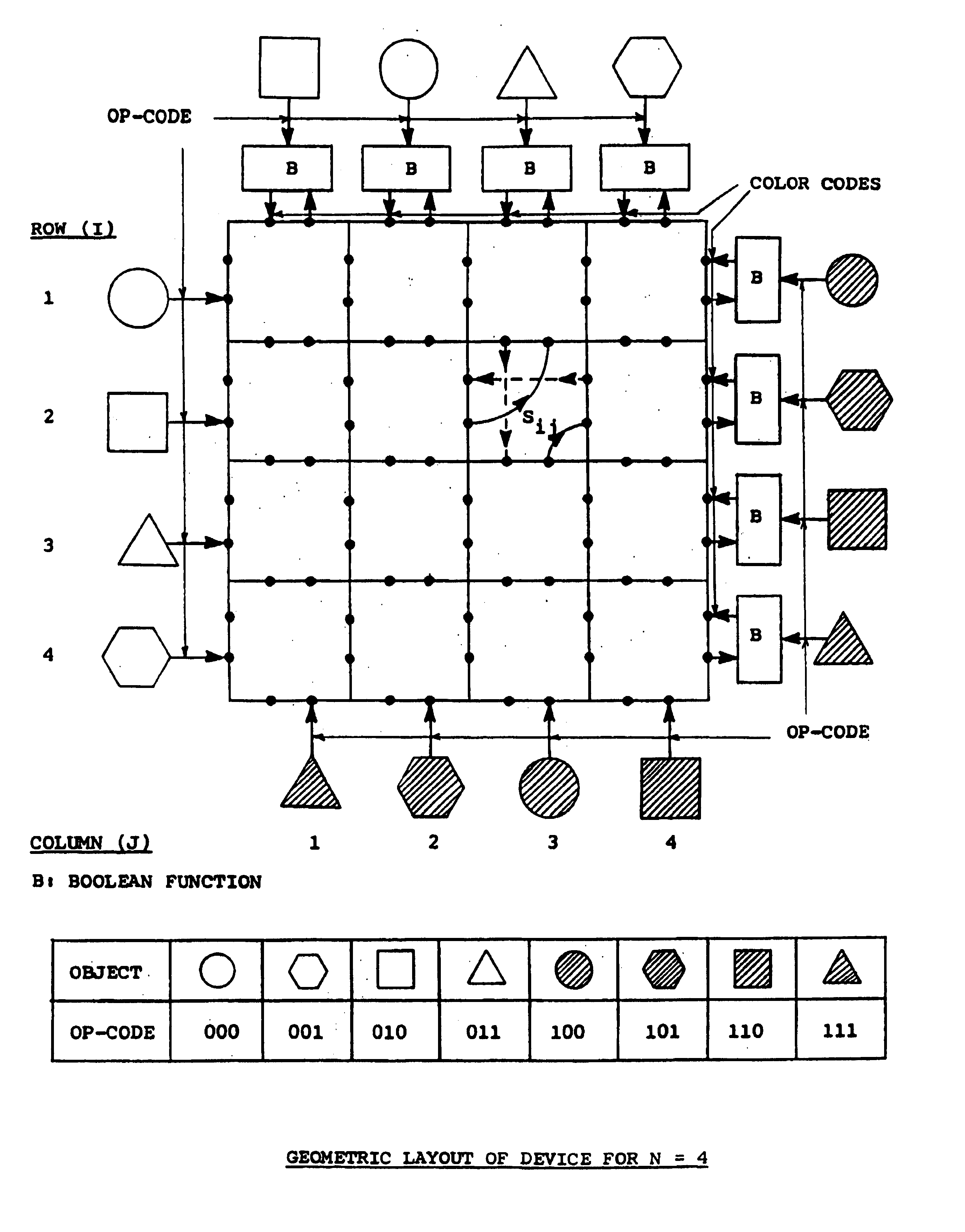
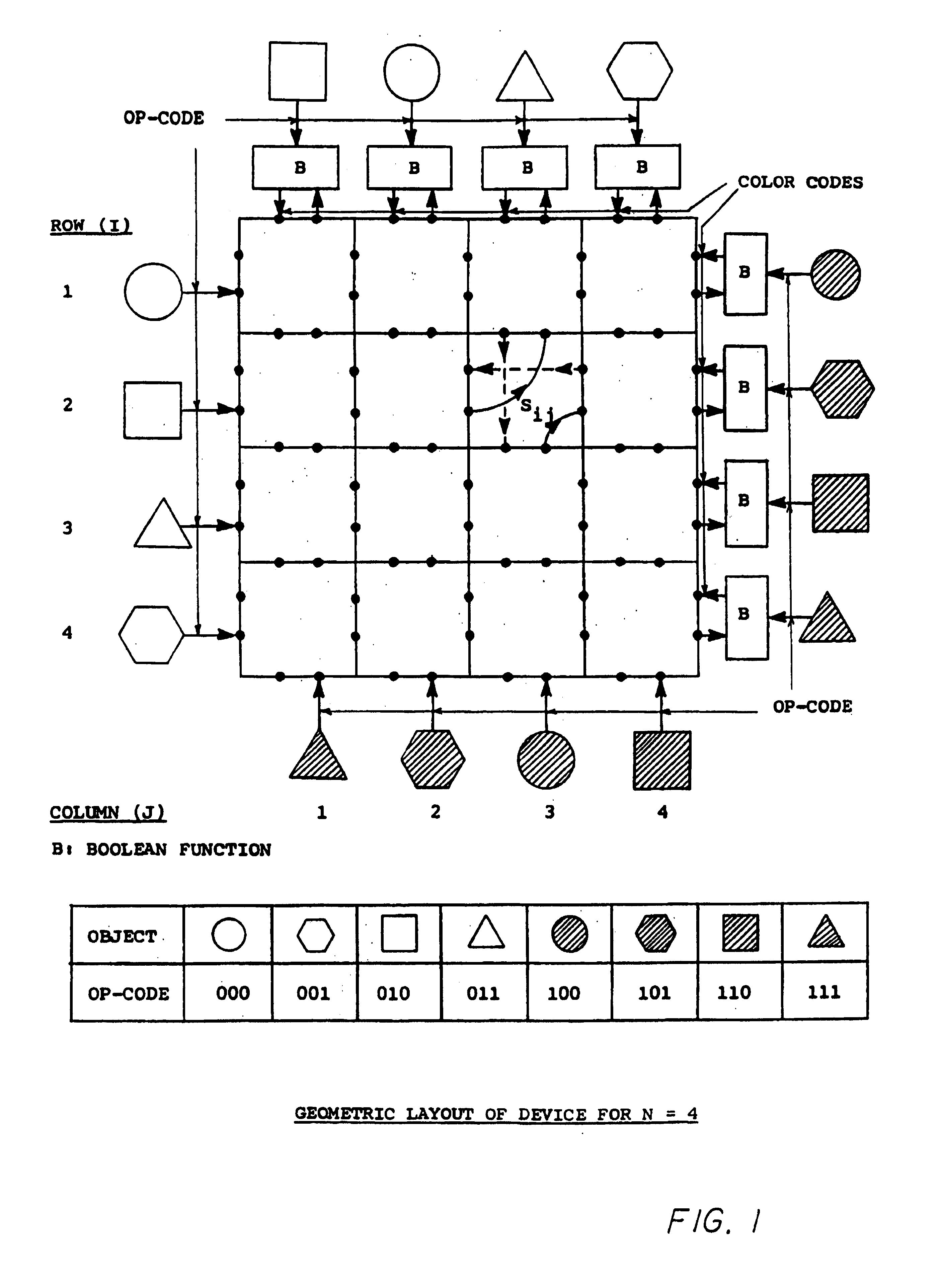
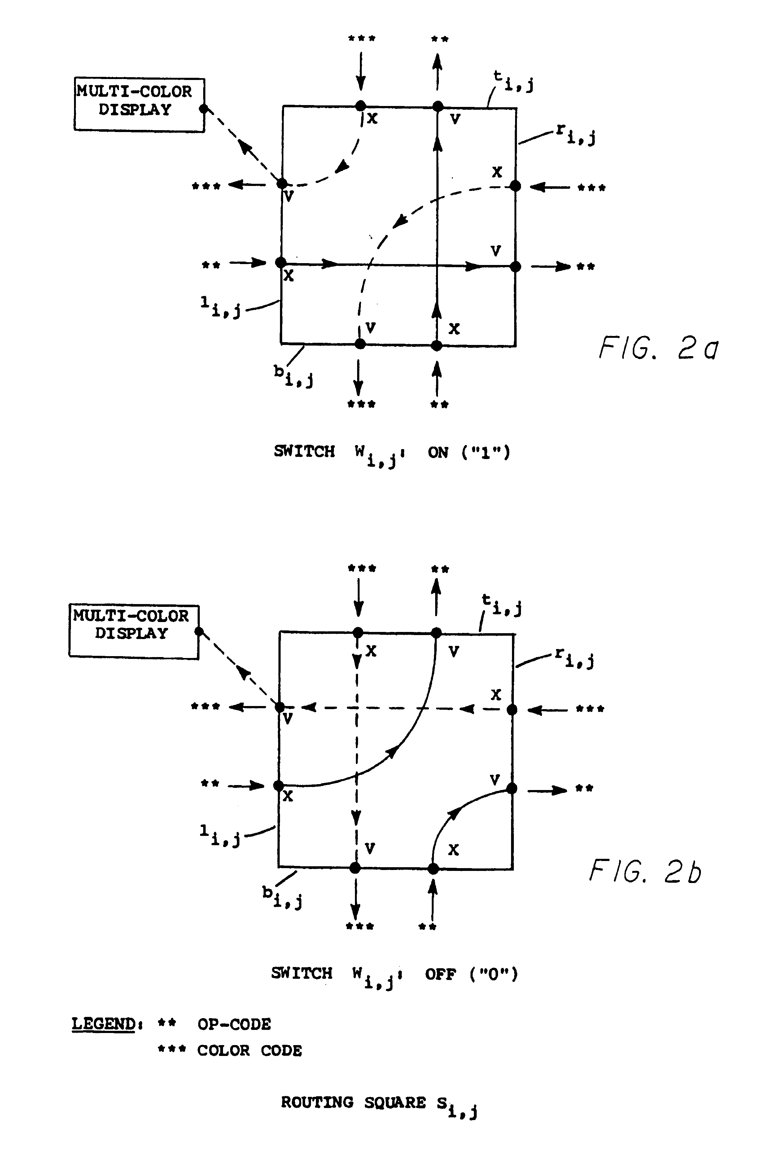
[0015]In accordance with a preferred embodiment of the invention, there is provided a device having a field of play arranged in an array of multi-color lighted switches on which a player attempts to discover the combination of switch positions which cause a singular color to be displayed on the field of play. The device utilizes a microprocessor programmed to generate random operating code patterns that correspond to objects placed along the edges of a square, simulate the routing of the operating codes from the left and bottom edges to the right and top edges of said square, generate color codes from pairs of operating codes, distribute color codes to multi-color displays, and control the progress of the game. The microprocessor is also programmed to monitor the position of the switches, control the display of multi-color indications, and generate distinct tone sequences representing color melodies and game completion melody. The microprocessor is also programmed to varry the degree of difficulty of each game by randomly rearranging either the switches which control the routing squares, the multi-color displays or both.

Problems solved by technology

However, such logic games are of mechanical designs and to the inventor's knowledge have never been implemented by “state of the art” electronics, i.e. integrated circuits, etc., which are presently available.

Method used


Image

  • Electronic hand held logic game
  • Electronic hand held logic game
  • Electronic hand held logic game

Examples


Embodiment Construction

[0032]Referring now to the drawings where the illustrations are for the purpose of describing the preferred embodiment of the invention and are not intended to limit the invention hereto, FIG. 3 is a front planviewperspective view of an electronic RAINBOWX device 10 is comprised of a casehousing 12 having a face 14 and carrying an array of individually operable multi-color lighted switches 22 which definingdefine a field of play. In a specific embodiment illustrated in FIG. 3, an arrays of four rows and four columns defines a field of play having sixteen individually operable multi-color lighted switches which may be referred to as 21-1 through 22-16; each row being numbered from left to right and from top to bottom.

[0033]A block diagram of the control circuitry for this RAINBOWX device 10 is illustrated in FIG. 4. This control circuitry includes a central processing unit 30 having a control program memory 32 associated therewith, a read only memory (ROM) 32, a random access memor...


PUM


Abstract

An electronic game, method and apparatus, is disclosed which includes individually operable electric switches to control the device, and electric light emitting means to provide multi-color displays. The object of the game is for the player to manipulate the switches until all multi-color displays indicate the same color. The device functions by matching electrical operating codes, transmitted from its left and bottom edges, with electrical operating codes stored at its top and right edges, to generate electrical color codes. The electric switches control the routing of the operating codes within the device, and the distribution of the color codes to the multi-color displays. In the preferred embodiment, the device utilizes a microprocessor to control the progress of the game, monitor the position of electric switches, and control the display of multi-color indications. The microprocessor also controls the generation of operating codes, the routing of operating codes from the left and bottom edges to the top and right edges, the determination of color codes at the top and right edges, and the distribution of those color codes from the top and right edges to the multi-color displays. The preferred embodiment also includes multi-color lighted switches to implement the electric control switches and the multi-color displays. The device also comprises an electric control means to select a new game, provisions to varry the level of difficulty of any particular game, and means to generate audible signals.

Description

[0001]This application is a continuation REI of Ser. No. 08 / 376,789 filed Jan. 23, 1995 now abandoned, which is a REI of Ser. No. 07 / 754,465 filed Sep. 3, 1991 now U.S. Pat. No. 5,286,037.BACKGROUND OF THE INVENTION[0002]This invention relates generally to an electronic game and in particular to an electronic logic game wherein a plurality of electric switches and multi-color displays are provided. It is possible, by depressing the switches in a particular manner or pattern, and by observing the resulting colors displayed, to determine the pattern of switches which results in a singular color being indicated on all multi-color displays.[0003]Various logic games are known wherein a plurality of playing pieces of various colors are connected together in a geometric shape, and are manipulated by the player so that pieces of the same color are grouped together. However, such logic games are of mechanical designs and to the inventor's knowledge have never been implemented by “state of th...

Claims


Application Information

Patent Timeline
Patent Type & Authority Patents(United States)
IPC IPC(8): A63F9/24A63F3/00A63F7/04A63F9/06
CPCA63F9/24A63F9/06A63F2009/2402A63F2009/2439A63F2009/2451A63F2009/2458A63F2009/2477A63F2009/2494
Inventor GHALY, NABIL N.
Owner GHALY NABIL N
Why Eureka
Try Eureka