Electronic control device

a control device and electronic technology, applied in the field of electronic control devices/units, can solve the problems of false recognition or perception by the driver, the fixed position of the display device itself, so as to improve the viewablility of display information, increase the convenience of the driver, and maintain the effect of driver safety

Inactive Publication Date: 2018-06-14
DENSO CORP
View PDF5 Cites 6 Cited by
  • Summary
  • Abstract
  • Description
  • Claims
  • Application Information

AI Technical Summary

Benefits of technology

[0008]For example, non-position specific or “non-directional” vehicle information, that is, information not likely to be misperceived based on its display position, may be freely positioned on a display device without restricting the display position of the information. As such, non-position specific information is unrestricted and may be moved to a driver-desired position or to an easily-viewable position. On the other hand, “directional” information, or position-specific information, e.g., vehicle information corresponding to images from the right side or the left side of the vehicle, may be prone to misperception by the driver if such vehicle information is reversely displayed, that is, displayed in a position that is opposite of, or reversed from, the position on or near the vehicle where the information is obtained. As such, the display position of “directional,” position-specific, vehicle information on a display device may be restricted to prevent or limit a user from moving, customizing, or otherwise repositioning the display location / position of the position-specific vehicle information to certain areas on the display device. By limiting display position restrictions to only “directional” information, improved viewablilty of display information may be obtained by allowing a driver to reposition and move display information to a driver-desired position, while limiting the display positioning of perception-critical display information. That is, the display position restriction scheme provides an increased convenience to the driver while also maintaining driver safety.

Problems solved by technology

However, one drawback of such a display is the fixed display position of the information on the display, as well as the fixed position of the display device itself.
That is, the information on the display and the display device itself cannot be moved or repositioned to a driver-desired position.
In such cases however, the customized positioning of the vehicle information may cause a false recognition or perception by the driver if, for example, the display position of vehicle information showing an image captured by a camera on the right side of the vehicle is displayed on a left side of the display device.
On the other hand, “directional” information, or position-specific information, e.g., vehicle information corresponding to images from the right side or the left side of the vehicle, may be prone to misperception by the driver if such vehicle information is reversely displayed, that is, displayed in a position that is opposite of, or reversed from, the position on or near the vehicle where the information is obtained.
As such, the display position of “directional,” position-specific, vehicle information on a display device may be restricted to prevent or limit a user from moving, customizing, or otherwise repositioning the display location / position of the position-specific vehicle information to certain areas on the display device.

Method used


Image

  • Electronic control device
  • Electronic control device
  • Electronic control device

Examples


Embodiment Construction

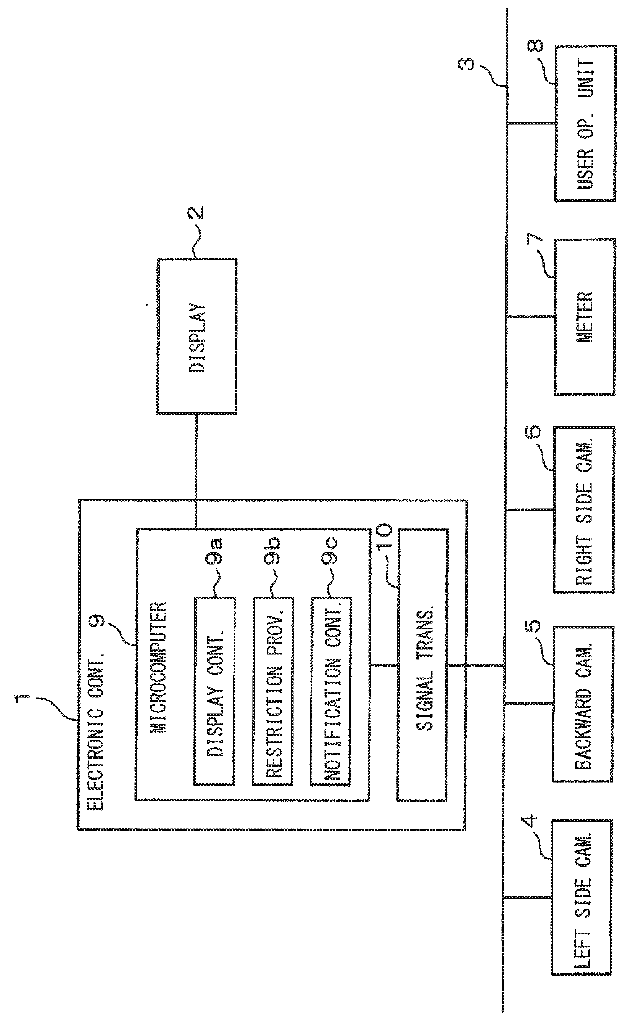
[0025]With reference to FIG. 1, an electronic control device 1 is a device that controls the display of information showing an image of a vehicle environment or surroundings. A display device 2 may be directly connected, and other devices such as a left side camera 4 (i.e., one of the on-board cameras), a backward camera 5 (i.e., one of the on-board cameras), a right side camera 6 (i.e., one of the on-board cameras), a meter device 7, and a user operation unit 8 may be connected via a bus 3. The bus 3 may operate following protocols and standards such as CAN, LIN, CXPI, FlexRay, MOST, and the like.

[0026]The electronic control device 1 has a microcomputer 9 and a signal transceiver 10. The microcomputer 9 has CPU, ROM, RAM, and like components. The CPU may execute a control program stored in ROM for controlling an operation of the electronic control device 1. The signal transceiver 10 controls transmission and reception of various signals to and from the bus 3.

[0027]The display devic...


PUM


Abstract

Positioning and displaying information at a driver-desired position for driver's convenience and for preventing the misperception of directional-based images by the driver to maintain driving safety is provided by an electronic control device including a display controller for controlling a display unit to display information including a vehicle environment image captured by an on-board camera; and a restriction provider for providing restrictions on a driver-customizable display position of the information on the display unit.

Description

CROSS REFERENCE TO RELATED APPLICATION[0001]The present application is based on and claims the benefit of priority of Japanese Patent Application No. 2016-239352, filed on Dec. 9, 2016, the disclosure of which is incorporated herein by reference.TECHNICAL FIELD[0002]The present disclosure generally relates to an electronic control device / unit used in a vehicle and other places.BACKGROUND INFORMATION[0003]Conventionally, an information display device for displaying information in a vehicle has been proposed, for example, as disclosed by a patent document 1 (i.e., Japanese Patent Laid-Open No. H04-368241), that is a system for displaying information such as an image of vehicle surroundings captured by an on-board camera.[0004]In such a system, the viewing angle of the display has no effect on a driver's view of the information (i.e., the image(s)). That is, the driver's position relative to the display does not affect how the driver sees the information on display device. However, one...

Claims


Application Information

Patent Timeline
Patent Type & Authority Applications(United States)
IPC IPC(8): G09G5/38G02B27/01B60R1/00
CPCG09G5/38G02B27/0101B60R1/00G09G2380/10G09G2340/0464G09G2354/00G02B2027/0138G02B2027/014B60R2300/105B60R2300/205B60R2300/8046G02B27/01G09G3/002G09G5/14H04N7/181G02B2027/0141
Inventor YAMAZATO, NARIHITO
Owner DENSO CORP
Why Eureka
Try Eureka