Method for regulating optical head inclination angle

A technology of tilt angle and adjustment method, which is used in optical recording/reproduction, instrument, data recording, etc., can solve the problems of unable to obtain EFM signal, unable to adjust the tilt control value, etc., and achieve the effect of reducing the data error rate

Inactive Publication Date: 2008-02-13
MEDIATEK INC
View PDF5 Cites 0 Cited by
  • Summary
  • Abstract
  • Description
  • Claims
  • Application Information

AI Technical Summary

Problems solved by technology

For blank chips (bare chips), the tilt control value cannot be adjusted because the EFM signal cannot be obtained

Method used


Image

  • Method for regulating optical head inclination angle
  • Method for regulating optical head inclination angle
  • Method for regulating optical head inclination angle

Examples


Embodiment Construction

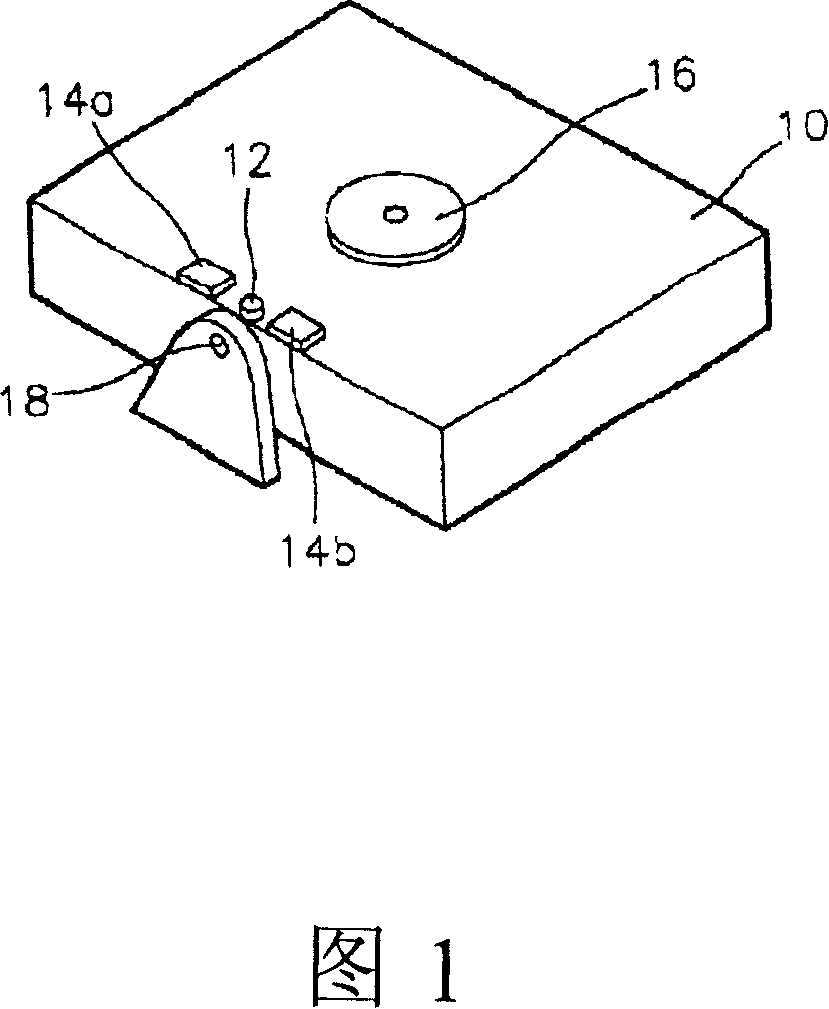
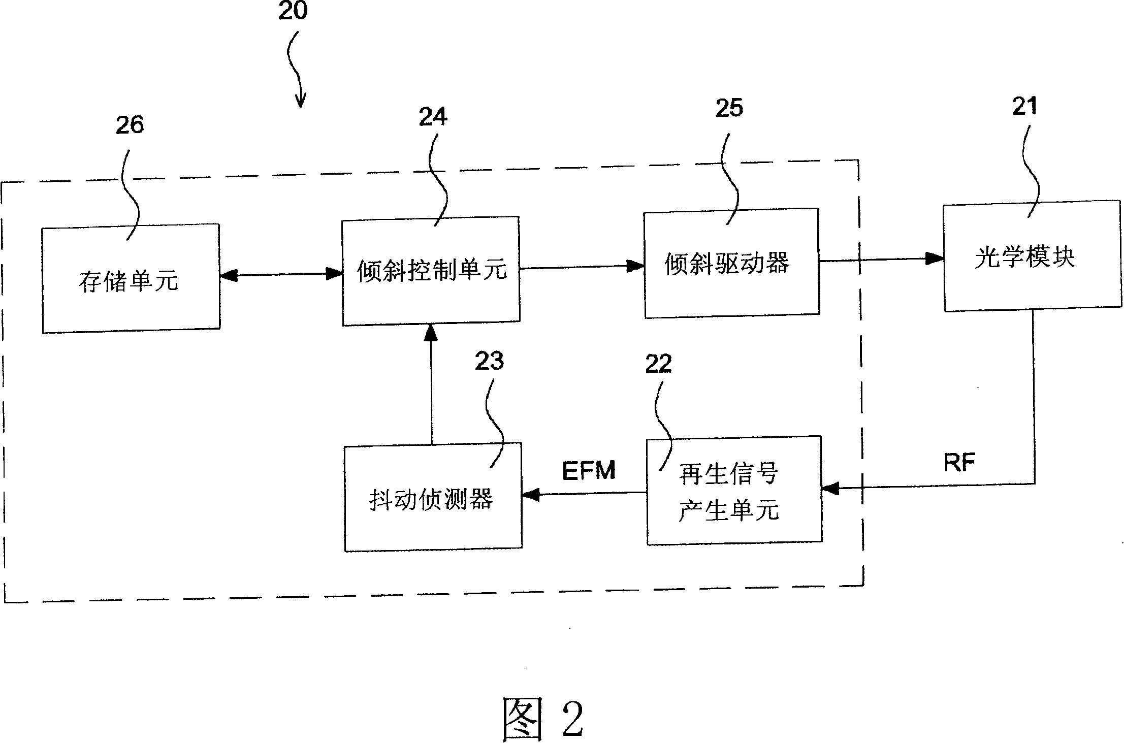
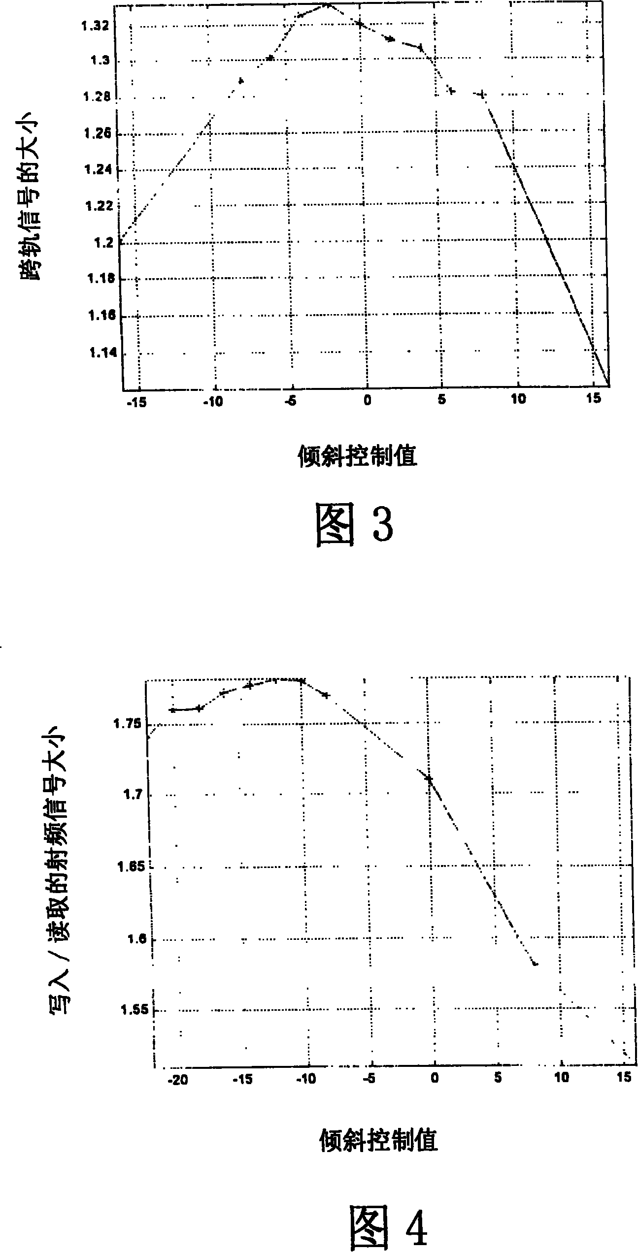
[0031] The method for adjusting the tilt angle of the optical head of the present invention will be described in detail below with reference to the drawings. Generally speaking, under a fixed power laser beam, if the optical head and the optical disc have no inclination angle, that is, at 90 degrees, the radio frequency signal (Radio frequency signal) read from the optical disc is the largest due to the maximum reflection of the laser beam. , RF) will have a maximum value, and the related signal derived from the radio frequency signal will also be the maximum value. The present invention adjusts the tilt control value of the optical head according to this characteristic. The relevant signals may include but not limited to the magnitude of the tracking cross signal, the magnitude of the write / read RF signal, the magnitude of the S-curve, and the level of the RF signal.

[0032] FIG. 3 is a graph showing the relationship between the tilt control value (tilt control value) and t...


PUM


Abstract

A method for controlling inclination of optical head so as to reduce the error rate for fetching and writing data. It is characterized by that containing track capable of moving optical head to inclination control value required for regulation; outputting laser beam with fixed power; setting change range of inclination control value; according to said change range controlling inclination angle of optical head and picking up radio-frequency signal correspondent to every inclination control value, and storing related signal value, and searching related signal value in which the maximum value is existed or not, if the maximum value is existed, storing inclination control vaue correspondent to said maximum value and using it as inclination control value of said track, if the maximum value is not existed, redacting change range of inclination control value and again executing the above setps.

Description

technical field [0001] The invention relates to a method for adjusting the inclination angle of an optical head. Background technique [0002] The optical pickup of the optical recording and reading device needs an actuator (actuator) to adjust the objective lens (object lens), so that the information read or recorded by the optical device, such as EFM (Eight to Fourteen Modulation) signal, Can be strong (robust). The actuator moves the optical head to the exact desired position (angle). However, when the optical disc to be read or recorded is curved, or the tilt angle of the optical head is incorrect, the read or recorded information will deteriorate. In order to compensate for the information deterioration, it is necessary to measure the relative inclination angle between the optical head and the optical disk, and adjust the inclination angle of the optical head in time. [0003] FIG. 1 shows the structure of a general tilt adjustment device. As shown in the figure, th...

Claims


Application Information

Patent Timeline
IPC IPC(8): G11B7/095
Inventor 林家豪高智贤何旭峰柯世豪
Owner MEDIATEK INC
Why Eureka
Try Eureka