
Parallel cross operation method of critical continuous conducting mode power factor corrector

A technology of power factor correction and critical continuity, applied in the direction of output power conversion devices, instruments, electrical components, etc., can solve the problems of complex implementation, uniform interleaving of inductive current, and increase in the number of components

Inactive Publication Date: 2008-02-27
TSINGHUA UNIV
View PDF1 Cites 3 Cited by
  • Summary
  • Abstract
  • Description
  • Claims
  • Application Information

AI Technical Summary

Problems solved by technology

In order to avoid problems in the logic circuit and improve the reliability of the parallel interleaved circuit, each converter needs an independent analog IC controller, which greatly increases the number of components in the circuit, especially when the number of parallel interleaved circuits is large. very complex to implement
Moreover, the difference between multi-controller PWM and the communication delay between controllers will affect the degree of uniform interleaving of inductor current and reduce the quality of input current.

Method used


Image

  • Parallel cross operation method of critical continuous conducting mode power factor corrector
  • Parallel cross operation method of critical continuous conducting mode power factor corrector
  • Parallel cross operation method of critical continuous conducting mode power factor corrector

Examples


Embodiment Construction

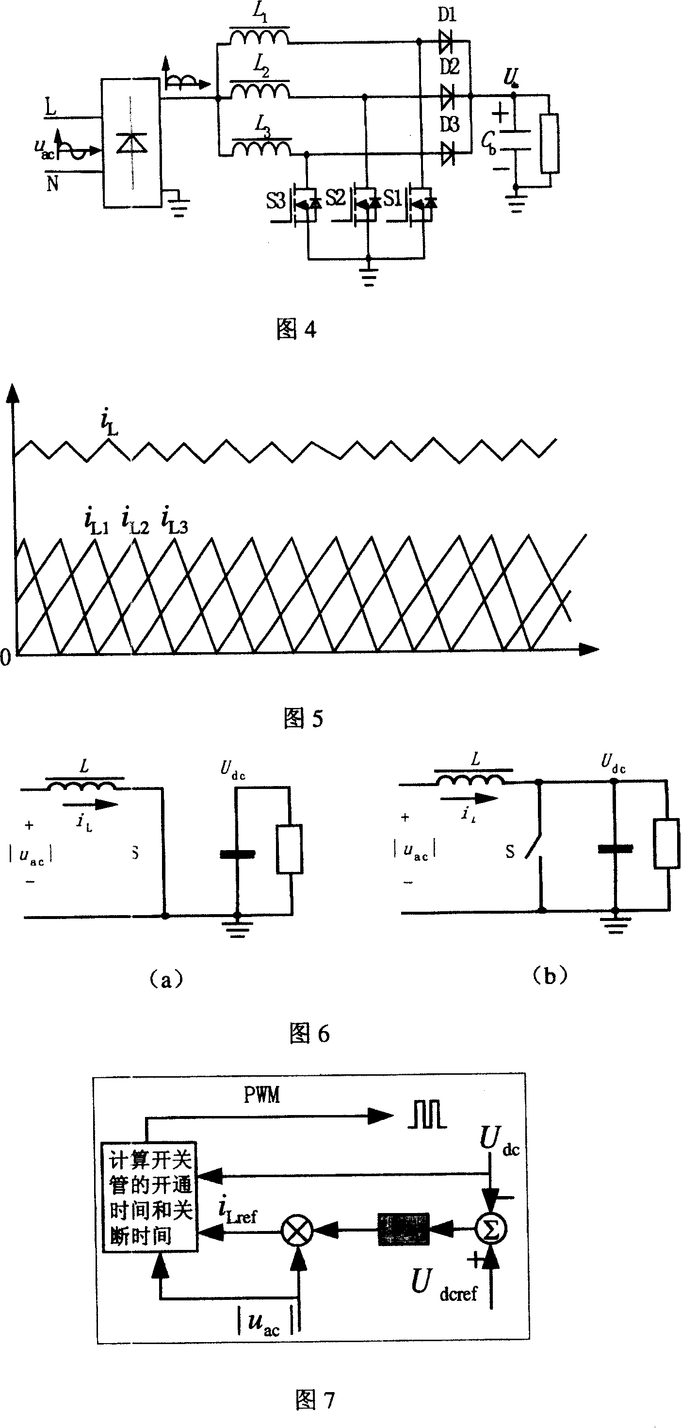
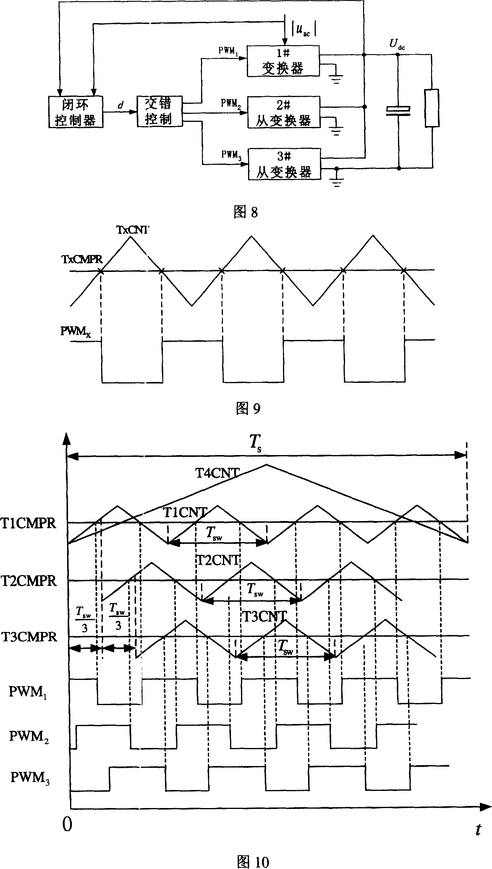
[0053] The deadbeat controller proposed by the present invention is obtained based on two operating modes of the BCM Boost APFC converter. The two operating modes of the BCM Boost APFC converter are shown in Figure 6, and the proposed deadbeat control scheme is shown in Figure 7 shown. The proposed parallel and interleaved operation scheme of multiple BCM Boost converters based on a single DSP realized by variable sampling frequency is shown in Figure 8, Figure 9 and Figure 10.

[0054] In the working mode shown in Figure 6(a), the inductor current i L = | u ac | L t on , In the working mode shown in Figure 6(b), i L = U dc - | ...


PUM


Abstract

The parallel connection interleaving operational method of the power factor corrector in the critical and consecutive conducting mode belongs to the field of the control technology of the power converter. It chooses the method of digital dead beat control, adopts single DSP, confirms one of the several shunt-wound BCM Boost convertors as the master convertor, which is controlled in closed loop, and the rest as the appurtenant convertors, which are controlled in open loop. Under the condition of variable switch frequency and sampling frequency, make the inductive current of the appurtenant convertors follow the inductive current of the master convertors and realize the parallel connection interleaving operation of the BCM Boost APFC convertor. It only samples the input voltage and the output voltage, does not need to detect the peak value of the switched current in the hardware or to judge the crossover point of the inductive current, can get relatively high power and control it more simply.

Description

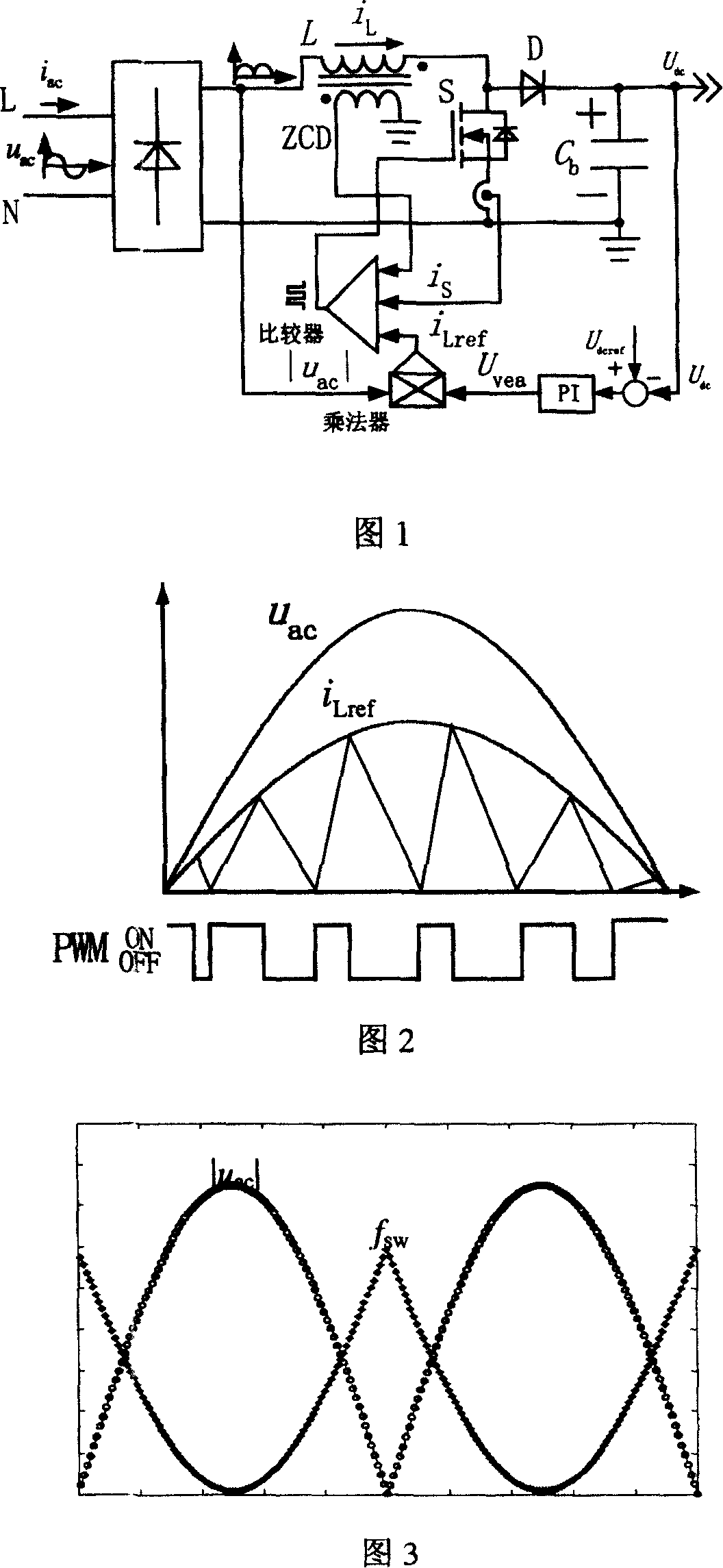
technical field [0001] The invention belongs to the research and application of a single-phase AC / DC APFC (Active Power Factor Correction) part in a switching power supply, and belongs to the technical field of power converter control. Background technique [0002] Boundary Continuous Conduction Mode (Boundary Conduction Mode, BCM) Boost APFC converter, referred to as BCM Boost APFC converter. Because it can realize the zero current and zero voltage (ZCS, ZVS) of the switching tube and eliminate the loss caused by the reverse recovery of the high-voltage fast recovery diode. Compared with the continuous (CCM) and discontinuous (DCM) BoostAPFC converter, It has high conversion efficiency. Figure 1 and Figure 2 show the system structure and key operating waveforms of the BCM Boost APFC converter. Fig. 3 has given the relationship curve of switching frequency and input voltage of BCM Boost APFC converter. [0003] The control strategy of the BCM Boost APFC converter shown in...

Claims


Application Information

Patent Timeline
Patent Type & Authority Patents(China)
IPC IPC(8): G05F1/70H02M1/00H02J3/46
CPCY02P80/10
Inventor 蒋志宏刘亚东黄立培
Owner TSINGHUA UNIV
Learn More