Dual-polarized dipole array antenna

A dipole antenna, dual-polarization technology, applied in antenna arrays, antennas, antenna unit combinations with different polarization directions, etc., can solve problems such as polarization staggered performance deterioration, improve radiation pattern parts, and reduce cable costs. , the effect of improving polarization staggered performance

Inactive Publication Date: 2008-03-05
凯仕林欧洲股份有限公司
View PDF5 Cites 1 Cited by
  • Summary
  • Abstract
  • Description
  • Claims
  • Application Information

AI Technical Summary

Problems solved by technology

The part of the cross-polarized radiation pattern also shifts with the horizontal patt...

Method used


Image

  • Dual-polarized dipole array antenna
  • Dual-polarized dipole array antenna
  • Dual-polarized dipole array antenna

Examples


Embodiment Construction

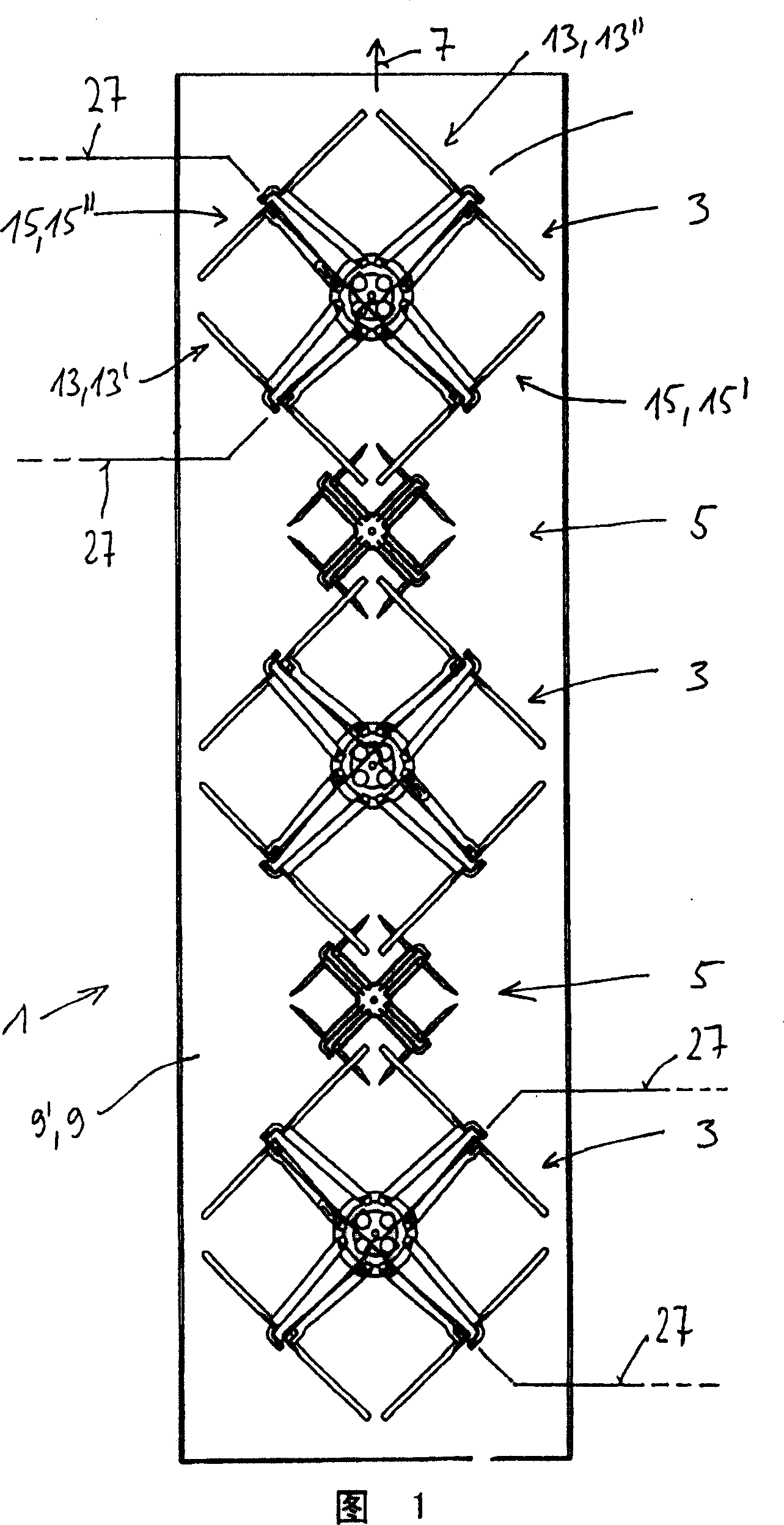
[0029] FIG. 1 shows a schematic plan view of a dual-polarized dipole antenna 1 having a plurality of first dipole squares 3 and a plurality of second dipole squares 5 . The first dipole square 3 is used, for example, for transmission in the 900 MHz frequency band. The two dipole squares 3 of smaller size are, for example, intended for transmission in the 1800 MHz frequency band. All dipole squares 3, 5 are oriented at an angle of 45° relative to the vertical and horizontal and are arranged superimposed along a vertical suspension direction 7 in front of a reflector 9 and at a suitable distance from the reflector plate 9'.

[0030] With regard to the basic structure and mode of operation, reference may be made to the earlier published prior art according to DE19823749A1, the content of which is fully referred to and which belongs to the content of the present invention.

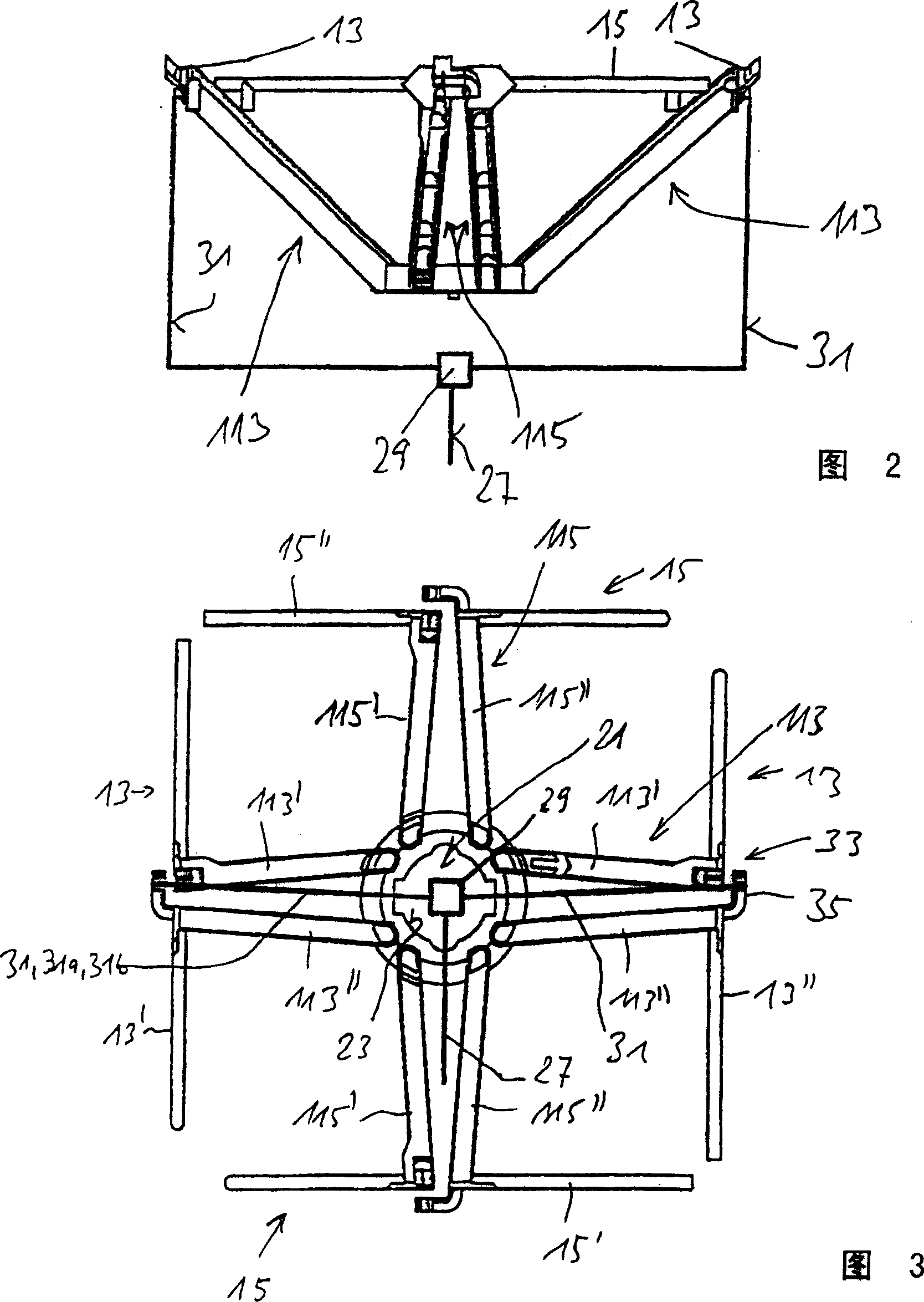
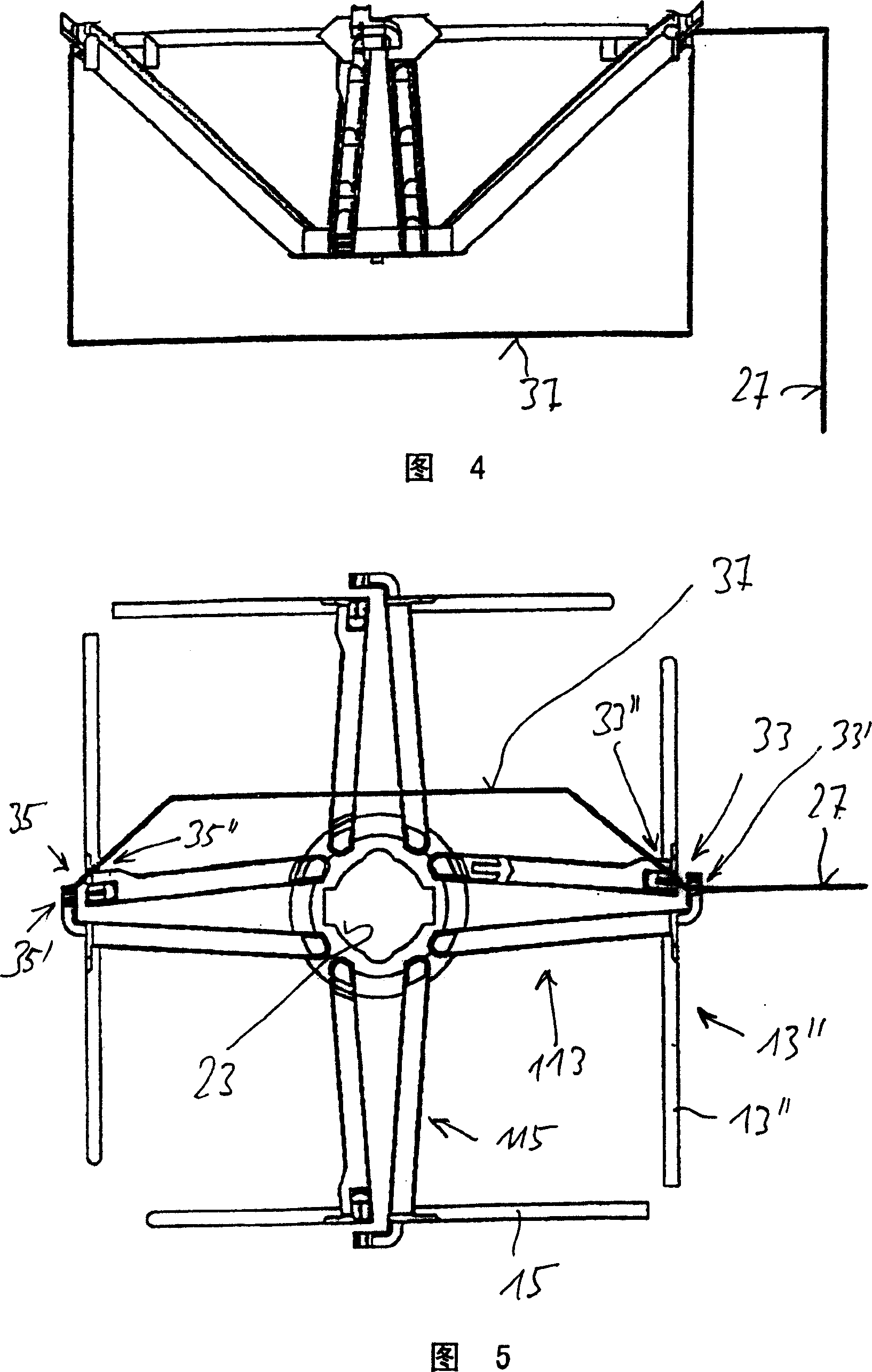
[0031] Such a dipole square known in principle has an inventive configuration and feeding as shown in FIGS...


PUM


Abstract

The antenna has one or more dipole squares at 45 degrees to the vertical or horizontal. A supply cable (27) is fed to a supply point (33) on one of two opposing parallel dipoles of a dipole square and a connecting cable (37) leads from this point to the supply point (35) on the opposing dipole and is electrically connected to the dipole halves of the dipole square at that point.

Description

technical field [0001] The invention relates to a dual-polarized dipole antenna. Background technique [0002] From DE19823749A1, a dual-polarized dipole antenna is known, which is especially suitable for mobile radio communication networks used worldwide, especially the GSM900 network (GSM: Global System for Mobile Communications) which transmits in the 900MHz or 1800MHz frequency band ) or GSM1800 network. [0003] Furthermore, a polarization orientation of ±45° is used in this known dual-polarized antenna. In the common antenna housing of a reflector there are usually a plurality of such dipole squares transmitting in a certain frequency band in the vertical direction and for example in each case two such vertically overlapping dipole squares A different dipole square for transmission in other frequency bands is arranged in between. [0004] The most commonly used horizontal half value width of the antenna is 65°. To make these antennas as compact as possible, two sin...

Claims


Application Information

Patent Timeline
IPC IPC(8): H01Q1/24H01Q9/16H01Q21/24H01Q21/06H01Q9/26H01Q9/28H01Q21/00
CPCH01Q21/062H01Q9/16H01Q1/246H01Q9/28H01Q9/26H01Q21/0006H01Q5/0075H01Q21/24H01Q5/42H01Q21/10
Inventor M·戈特尔
Owner 凯仕林欧洲股份有限公司
Why Eureka
Try Eureka