Full wave dipole array having improved squint performance

a dipole array and full wave technology, applied in the direction of antennas, antenna details, antenna feed intermediates, etc., can solve the problems of cross polarization and squint degradation at certain frequencies, and achieve the effect of minimizing the squint of a beam pattern and improving squint performan

Active Publication Date: 2016-08-25
COMMSCOPE TECH LLC
View PDF4 Cites 11 Cited by
  • Summary
  • Abstract
  • Description
  • Claims
  • Application Information

AI Technical Summary

Benefits of technology

[0006]A cellular base station antenna having improves squint performance is provided. The antenna includes a ground plane, a first plurality of radiating elements supported over the ground plane by microstrip support PCBs, and a second plurality of radiating elements supported over the ground plane by stripline support PCBs. The first and second pluralities of radiating elements are arranged in at least one array of low band radiating elements, and the quantities of microstrip PCB elements and stripline PCB elements are selected to minimize squint of a beam pattern provided by the array. The first plurality of radiating elements may be located below the second plurality of radiating elements in the array. The array may be arranged in a linear column or a staggered column. In one example, the first plurality of radiating elements comprises four radiating elements and the second plurality radiating elements comprises two radiating elements.

Problems solved by technology

While full wave dipoles have certain advantages in low band arrays of radiating elements in a multi-band array, known arrays of full wave dipoles typically experience disadvantageous coupling between two adjacent −45 degree polarization dipoles and +45 degree polarization dipoles, which may cause cross polarization and squint degradation at certain frequencies (referred to herein as “squint resonance frequency”).

Method used


Image

  • Full wave dipole array having improved squint performance
  • Full wave dipole array having improved squint performance
  • Full wave dipole array having improved squint performance

Examples


Embodiment Construction

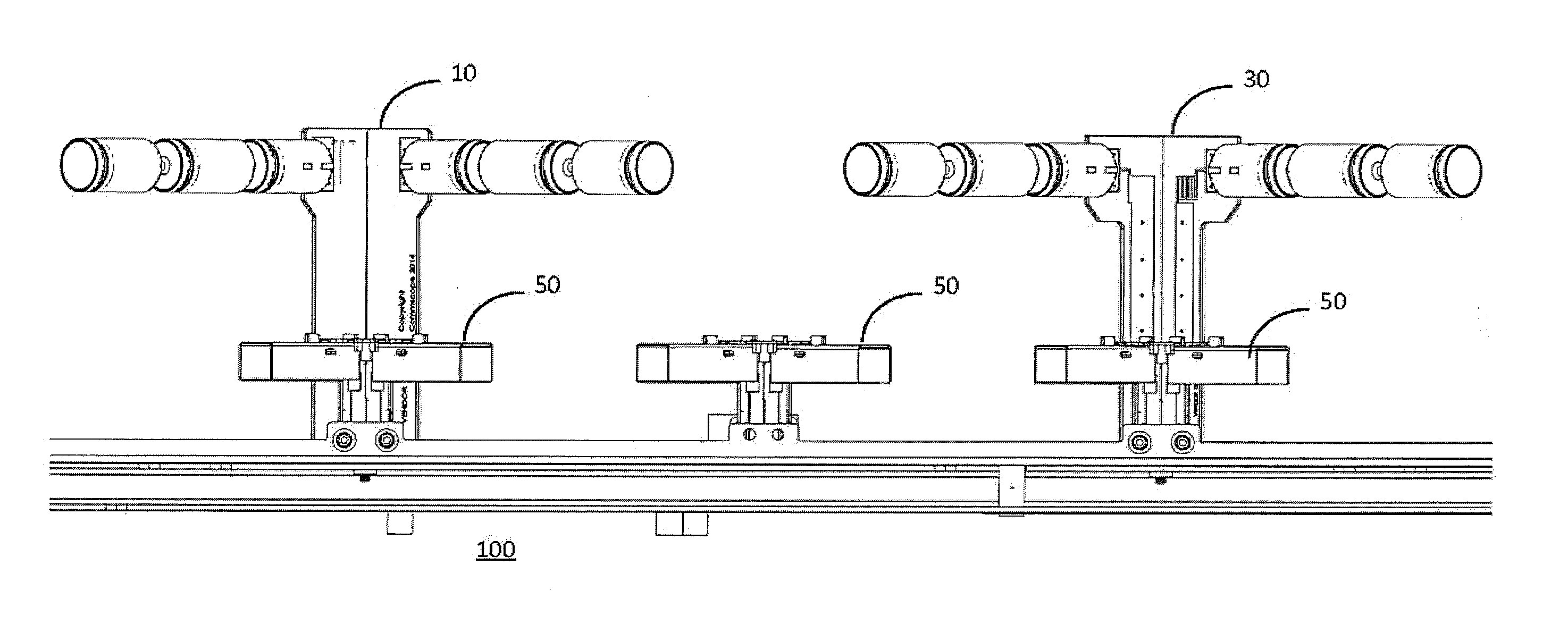
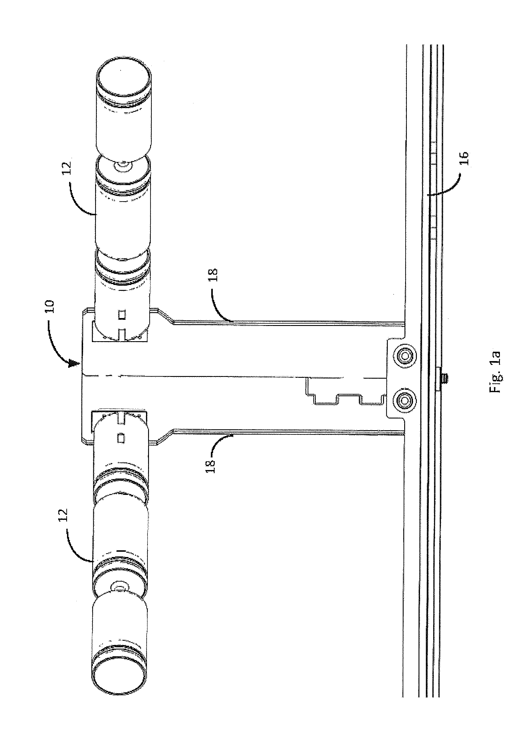
[0020]FIG. 1a illustrates one example of a microstrip support PCB radiating element 10. The microstrip support PCB radiating element 10 includes low band dipole arms 12 supported over a reflector 16 by microstrip support PCBs 18. In the illustrated examples, low band dipole arms 12 comprise full wave dipoles, which span from about three-quarters to one full wavelength of an operating frequency band of microstrip support PCB radiating element 10. Optionally, the low band dipole arms 12 include RF chokes that are resonant at high band frequencies to minimize scattering of high band elements. See, e.g., International Pat. Pub. No. WO 2014100938, (the “'938 Application.”), which is incorporated by reference.

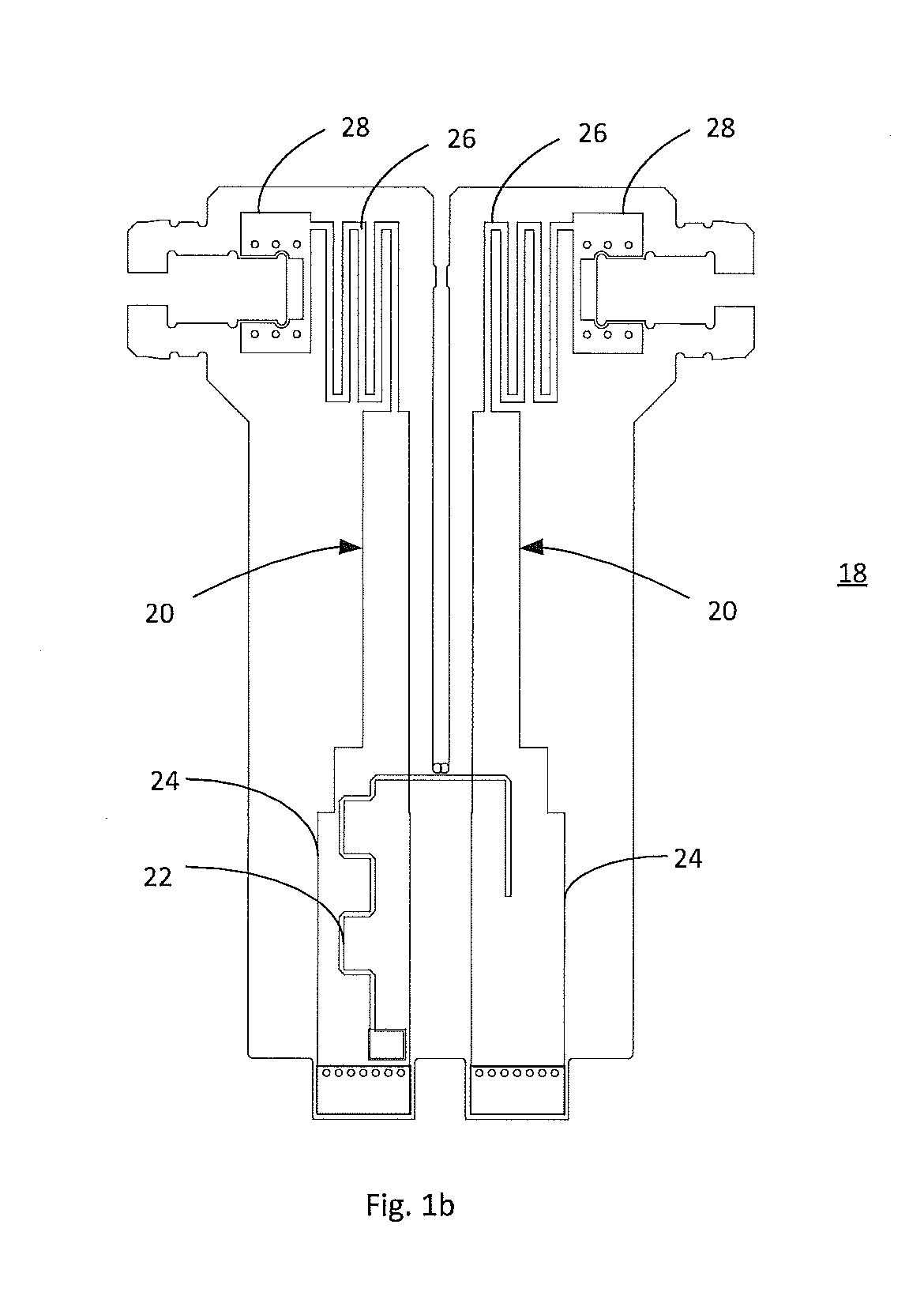
[0021]In the microstrip support PCB radiating element 10, the low band dipole arms 12 are excited by microstrip support PCBs 18 (FIG. 1b). The term “microstrip,” as used herein, has its conventional meaning of a conducting strip separated from a ground plane by a dielectric layer, of...


PUM


Abstract

A cellular base station antenna having improves squint performance is provided. The antenna includes a ground plane, a first plurality of radiating elements supported over the ground plane by microstrip support PCBs, and a second plurality of radiating elements supported over the ground plane by stripline support PCBs. The first and second pluralities of radiating elements are arranged in at least one array of low band radiating elements, and the quantities of first and second pluralities of radiating elements are selected to reduce squint of a beam produced by the at least one array. The first plurality of radiating elements may be located below the second plurality of radiating elements in the array. The array may be arranged in a linear column or a staggered column. In one example, the first plurality of radiating elements comprises four radiating elements and the second plurality radiating elements comprises two radiating elements.

Description

STATEMENT OF RELATED APPLICATIONS[0001]This application claims priority to U.S. Provisional Patent Application Ser. No. 62 / 120,689, filed Feb. 25, 2015, the disclosure of which is incorporated by reference.FIELD OF THE INVENTION[0002]The present invention relates to antennas comprising arrays of radiating elements. In particular, the present invention provides improved squint performance for arrays of radiating elements.BACKGROUND[0003]Arrays of full wave dipole radiating elements have been observed to suffer from squint at high electrical down tilt angles. The term “squint” means the amount that a beam peak (midpoint between −3 dB angles) deviates from boresight of the antenna. See, for example, FIG. 9, which illustrates an azimuth beam pattern having approximately 12° of squint. A “full wave” dipole radiating element is a type of dipole that is designed such that its second resonant frequency is in the desired frequency band. In this type of dipole, the dipole arms are dimensioned...

Claims


Application Information

Patent Timeline
Patent Type & Authority Applications(United States)
IPC IPC(8): H01Q21/08H01Q9/16
CPCH01Q9/16H01Q21/08H01Q1/246H01Q5/42H01Q21/24
Inventor BISIULES, PETER J.SHOOSHTARI, ALIREZA
Owner COMMSCOPE TECH LLC
Why Eureka
Try Eureka