Broadband symmetrical dipole array antenna

Inactive Publication Date: 2006-03-23
SMARANT TELECOM
View PDF6 Cites 11 Cited by
  • Summary
  • Abstract
  • Description
  • Claims
  • Application Information

AI Technical Summary

Benefits of technology

[0006] In view of the aforesaid problems occurring with the conventional techniques, the invention aims to provide a broadband symmetrical di

Problems solved by technology

While radio transmission is relatively free from geographical restrictions, when the antenna is installed on a location with geographical obstacles (such as corners of walls, ceiling, etc.), its directional gain drops, and the communication quality of signa

Method used


Image

  • Broadband symmetrical dipole array antenna
  • Broadband symmetrical dipole array antenna
  • Broadband symmetrical dipole array antenna

Examples


Embodiment Construction

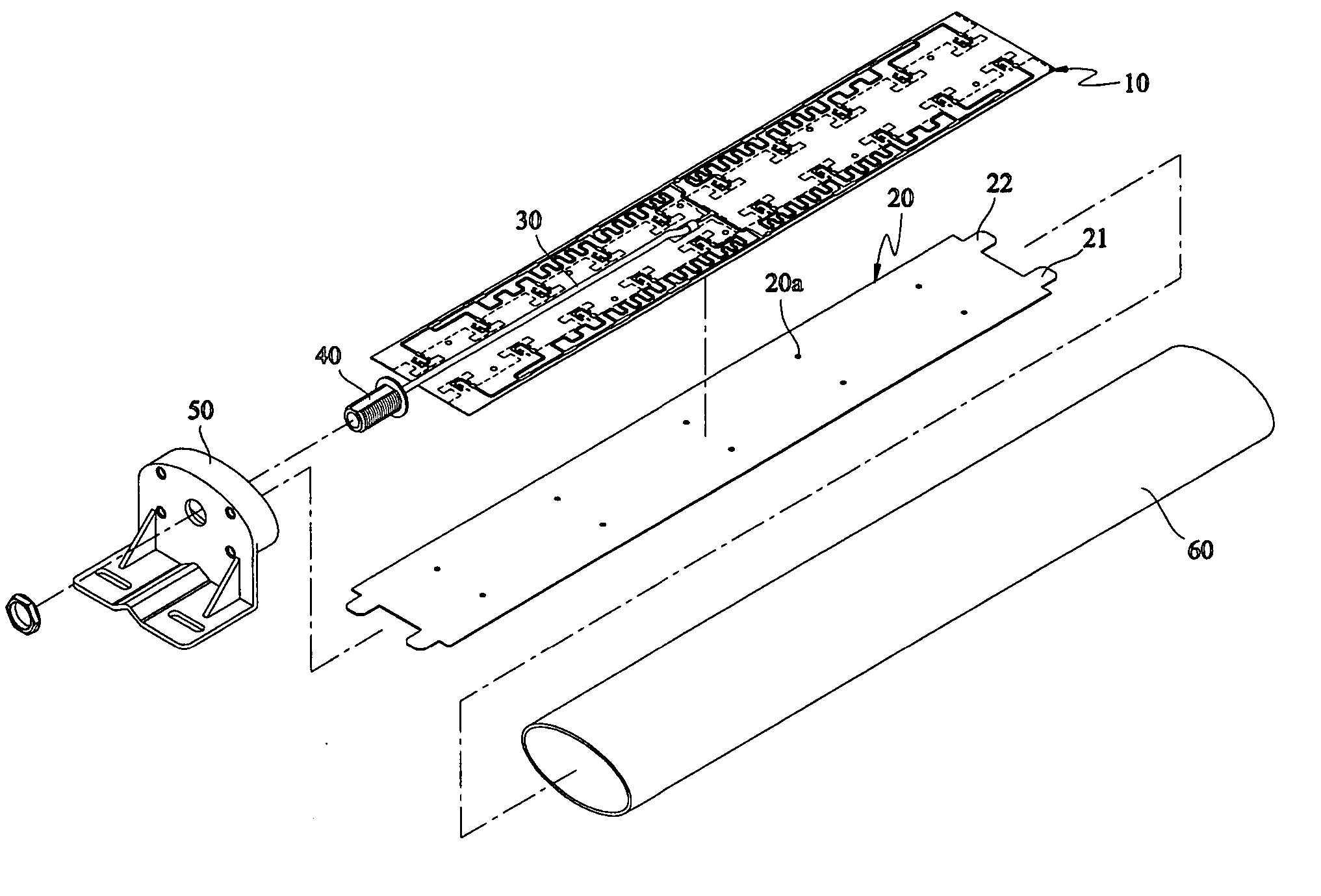
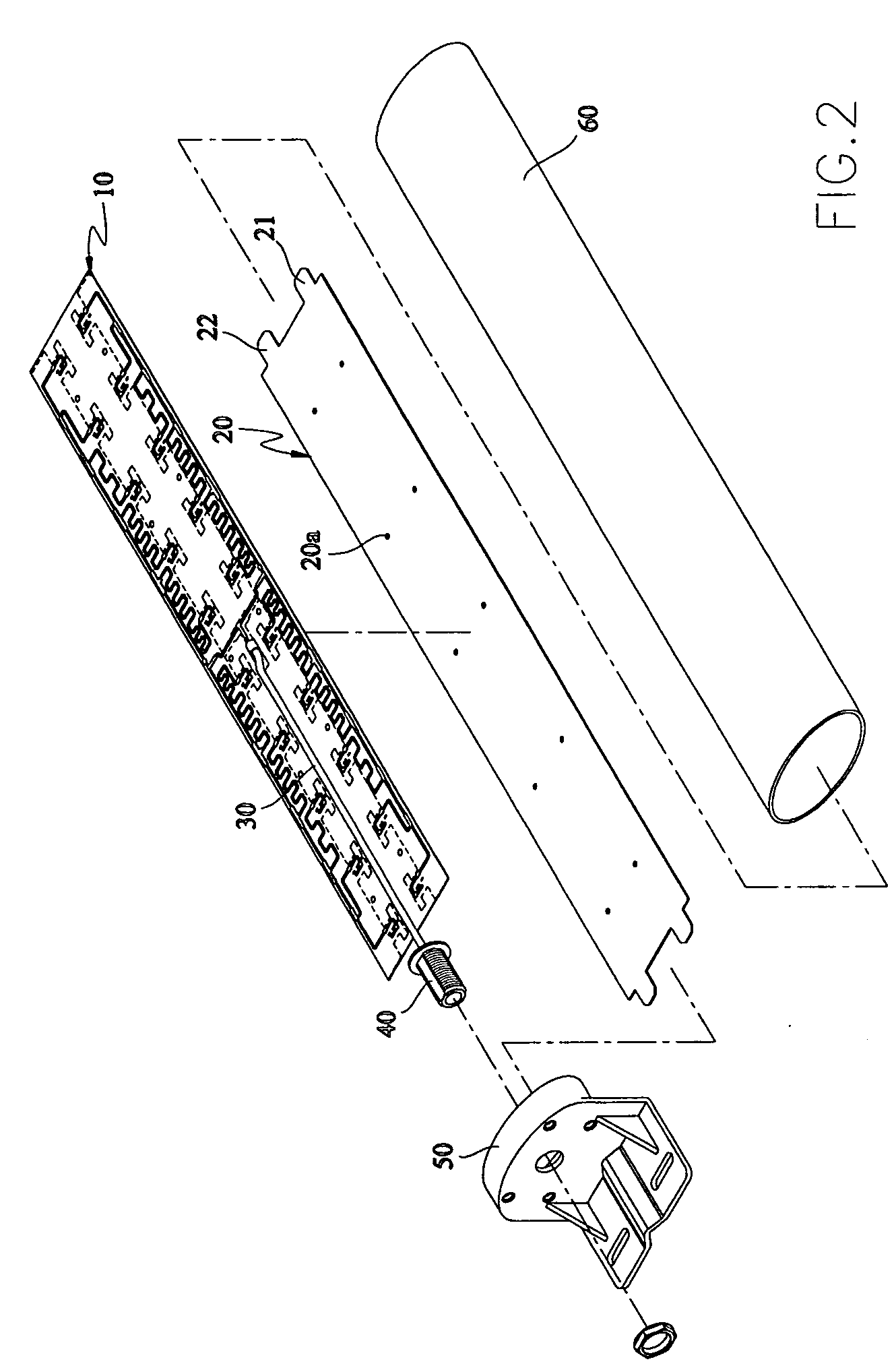
[0018] Referring to FIG. 2, the antenna according to the invention includes an antenna 10, a reflection plate 20, a metal conductive wire 30, a connector 40, a seat 50 and a shell 60. The reflector 20 is spaced from one side of the antenna 10 in a parallel manner at a selected distance. The antenna 10 is a printed circuit antenna made from non-metallic material (such as Rogers RO-4350B). It has a first surface 101 and a second surface 102 formed with a required circuit pattern by chemical etching.

[0019] The reflection plate 20 has lugs 21 and 22 extended from two ends to wedge in slots formed on the seat 50 and the shell 60 and anchor thereon. The reflection plate 20 is flat and about the size of the antenna 10. It is made of metal that has a shielding effect upon electromagnetic waves, and can therefore reflect radiation signals generated by the antenna 10 in a selected direction to boost the directional gain of the antenna.

[0020] The seat 50 is formed substantially in an L-shape...


PUM


Abstract

A broadband symmetrical dipole array antenna adopted for use in radio transmission includes a symmetrical feed network, symmetrical radiation units and a reflection plate. The symmetrical feed network and the symmetrical radiation units form an antenna field of a narrower radiation angle range. The reflection plate is spaced from one side of the antenna in a parallel fashion at a selected distance to reflect the radiation signals and enhance antenna directionality.

Description

FIELD OF THE INVENTION [0001] The invention relates to a broadband symmetrical dipole array antenna adopted for used on electronic devices to perform radio transmission, and particularly a broadband symmetrical dipole array antenna that is equipped with a reflection plate. BACKGROUND OF THE INVENTION [0002] With continuous advances in the wireless communication industry, users can transmit information through radio transmission systems without geographical restrictions. The antenna is an important element in such radio transmission systems. It transforms the voltage and current of a transmitter into electromagnetic waves and broadcasts them in radiation fashion. The electromagnetic waves may also be received and transformed to voltage and current, and transferred to a receiver for processing to accomplish signal transmission. Commonly used antennas include dipole antennas, helical antennas, and the like. [0003] While radio transmission is relatively free from geographical restrictio...

Claims


Application Information

Patent Timeline
IPC IPC(8): H01Q9/28
CPCH01Q1/246H01Q1/42H01Q21/08H01Q21/0006H01Q19/108
Inventor CHIEN, CHUN-CHIEN
Owner SMARANT TELECOM
Why Eureka
Try Eureka