Rotation pair combination unit and motion decoupling parallel mechanism formed thereby

A technology of combining units and rotating pairs, which is applied in the directions of manipulators, program-controlled manipulators, manufacturing tools, etc., can solve the problems of complex control, difficult calibration, and has not yet been reported in the literature.

Inactive Publication Date: 2008-07-09
HEBEI UNIV OF TECH
View PDF6 Cites 2 Cited by
  • Summary
  • Abstract
  • Description
  • Claims
  • Application Information

AI Technical Summary

Problems solved by technology

However, the movement between the drive units of the above-mentioned mechanism is coupled, that is, the movement of the overall output platform of the mechanism in any direction is the synthesis of the movements of all drive units, so the control of the mechanism is very complicated, calibration is difficult, and it also restricts Improved accuracy and reduced cost
[0004] There is no literature report on the decoupling parallel mechanism of pure revolving pair kinematics

Method used


Image

  • Rotation pair combination unit and motion decoupling parallel mechanism formed thereby
  • Rotation pair combination unit and motion decoupling parallel mechanism formed thereby
  • Rotation pair combination unit and motion decoupling parallel mechanism formed thereby

Examples


Embodiment 1

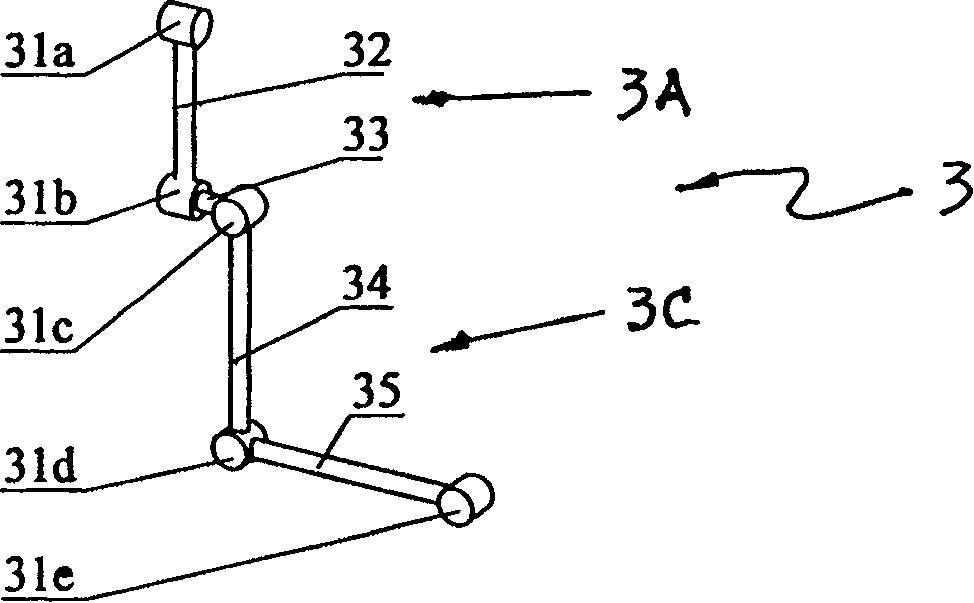
[0018] figure 1 A schematic diagram of an embodiment of a rotary pair combination unit (ie, the rotary pair combination unit 3 ) designed for the present invention. It includes two groups of rotating pairs: the first group of rotating pairs 3A includes 31a, 31b and the connecting rod 32 connecting the two rotating pairs; the second group of rotating pairs 3C includes 31c, 31d, 31e and the connecting rods connecting the three rotating pairs 34 and 35; two groups of rotating pairs 3A, 3C are vertically connected through the connecting rod 33 through the axes of said rotating pairs 31b, 31c to form a rotating pair combination unit 3 . Its design features are: the axes of the two groups of rotating pairs 3A, 3C are parallel to each other; the axes of the rotating pairs between the two groups are orthogonal to each other.

Embodiment 2

[0020] figure 2 A schematic diagram of an embodiment of another rotary pair combination unit (ie, the rotary pair combination unit 4 ) designed for the present invention. It also includes two groups of rotating pairs 3A, 3C: the first group of rotating pairs 3A also includes 31a, 31b and connecting rods 32 connecting the two rotating pairs; the second group of rotating pairs 3C also includes 31c, 31d, 31e and connecting rods The connecting rods 34, 35 of the revolving pair; the two groups of revolving pairs 3A, 3C are vertically connected through the connecting rod 33 through the revolving pairs 31b, 31c to form the revolving pair combination unit 4. Its design features are: the two groups of rotating pairs 3A, 3C, the axes of the rotating pairs in the same group are parallel to each other; the axes of the rotating pairs in different groups are orthogonal to each other.

[0021] The difference between Embodiment 2 and Embodiment 1, or between the swivel pair combination unit...

Embodiment 3

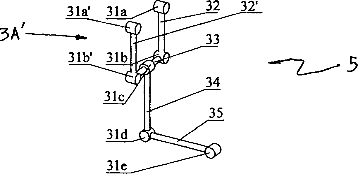
[0023] image 3 A schematic diagram of an embodiment of the third type of revolving pair assembly unit (ie, the revolving pair assembly unit 5 ) designed for the present invention. It is formed by adding a group of rotary sub-units 3A / with the same structure as the rotary sub-unit 3A on the basis of the rotary sub-combination unit 4 . The added revolving pair unit 3A / is connected symmetrically with the connection point 31c as a symmetrical axis, that is to say, this group of revolving pair units (3A+3A / ) includes symmetrical revolving pairs 31a and 31a', and symmetrical revolving pairs 31b and 31b', and the symmetrical connecting rods 32 and 32', and the connecting rod 33 connecting the revolving pairs 31b and 31b'. Its design features are: the axes of the two groups of revolving pairs are parallel to each other; the axes of different groups of revolving pairs are orthogonal to each other.

[0024] Compared with Examples 1 and 2, Example 3 has a larger and more stable driv...


PUM


Abstract

The invention refers to a kind of moving spider compound unit and movement decoupling parallel mechanism made up of above units, the character lies in: it includes two groups of moving spider units connected by a pole, the moving spider axis spaces are placed orthogonally, one moving spider includes two moving spiders whose axes are parallel and which is connected by a pole; the other moving spider includes three moving spiders whose axes are parallel and which is connected by two poles, the connecting point of the two groups of moving spiders is the third link. The movement decoupling parallel mechanism includes a base, a moving platform and three same or different moving spiders between them, the compound units are moving spiders' compound units, or the random combinations of the moving spiders.

Description

technical field [0001] The invention relates to the field of advanced manufacturing, in particular to a motion decoupling parallel mechanism composed of rotating pair combination units. The so-called motion decoupling parallel mechanism refers to the parallel mechanism in which the translation or rotation of the parallel mechanism in a certain direction only depends on the action of the drive unit in this direction, while the drive units in other directions do not make effective actions. The International Patent Classification is proposed to be IPC.CL 7 .B25J 9 / 08. Background technique [0002] Parallel mechanism refers to the mechanism in which two or more drive units are installed in parallel and jointly complete the action. It is widely used in technical fields such as heavy-duty simulation equipment, CNC machine tools, robots, sensors, and micro-operations. [0003] So far, there have been some research results on parallel mechanisms using pure rotary pairs: such as, t...

Claims


Application Information

Patent Timeline
Patent Type & Authority Patents(China)
IPC IPC(8): B25J9/08B25J11/00
Inventor 李为民高峰张建军
Owner HEBEI UNIV OF TECH
Why Eureka
Try Eureka