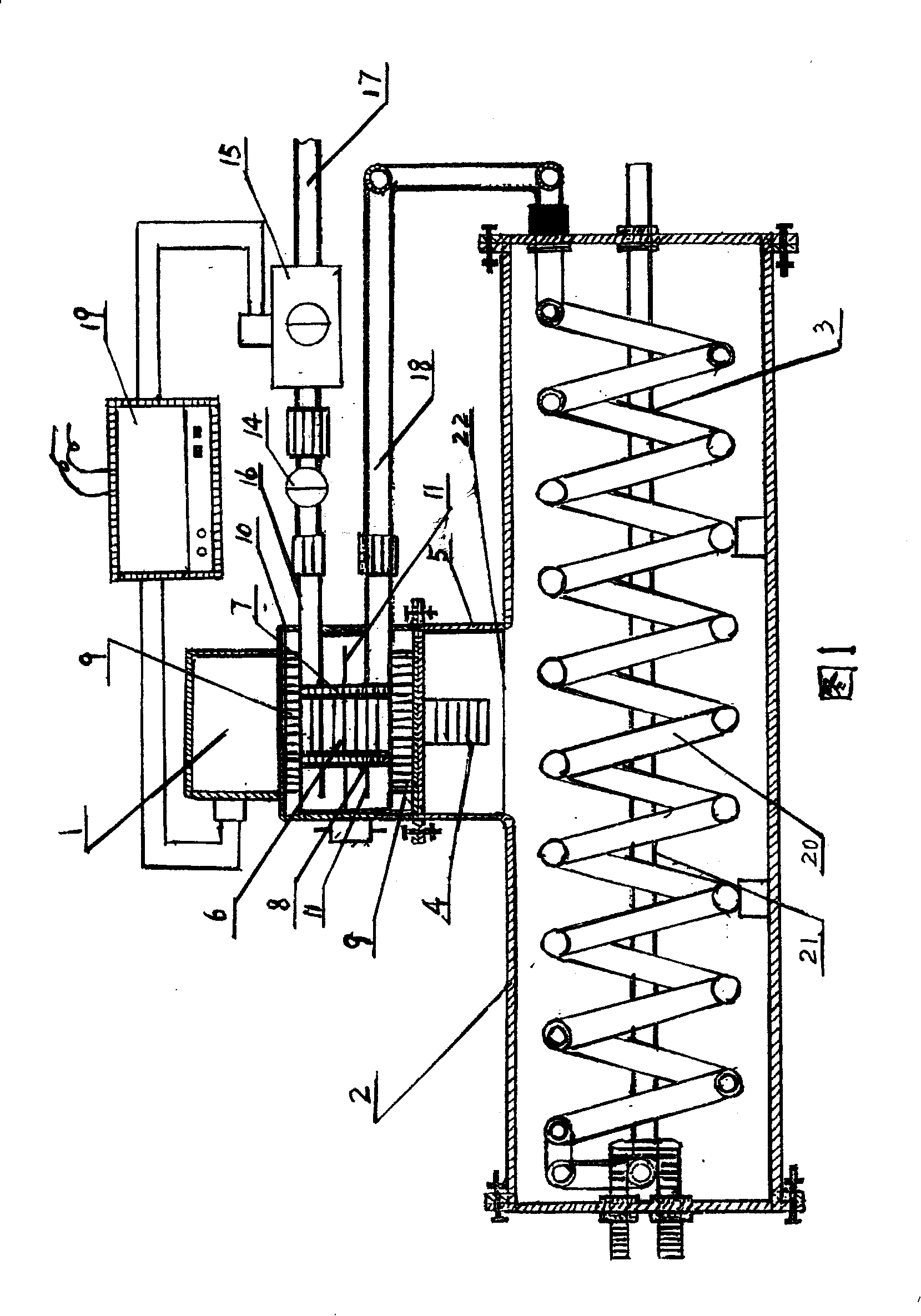
At present, the microwave water heater technology disclosed by using the above characteristics generally adopts a containment sheath outside the magnetron, which is placed in the inner tank of the water heater, or a convex cavity is directly set in the inner tank of the water heater, and a magnetron is set in the convex cavity. Tube, such as application number 98220885 and application number 00254319, etc., the disadvantage of the microwave water heater with the above structure is that the large amount of heat generated by the microwave generating device cannot be quickly dissipated through the hot bad conductor containing sleeve, resulting in excessive temperature of the microwave generating device Damage often occurs, or only a small area of the barrel wall dissipates heat, the heat dissipation speed is slow, and the waste heat generated cannot be quickly and effectively transferred to the water, causing the temperature of the microwave generating device to be too high to work continuously. Another example is in the design of the application number 98227512.9. Shown in accompanying drawing 1 of specification, adopt magnetron 1 water-cooled type, in the negative pole of magnetron, anode 6 add insulating tube 7 and heat dissipation casing 8, add cooling fin 11 in heat dissipation casing 8, and by sealing shell 10. Water cooling is carried out after sealing, although the cooling effect can be guaranteed, so that the magnetron can work continuously, but because the cooling water in the closed shell 10 passes through the pipeline 16, the regulating valve 14, the solenoid valve 15, and the water inlet pipe 17, it is directly connected with the water source , resulting in a large amount of heat generated when the magnetron is working, which is directly transferred from the cooling water in the closed casing 10 to the external water source, so that although the microwave water heater can work normally, the large amount of heat generated by the microwave generating device is dissipated and lost. Being effectively utilized, the thermal efficiency is not high
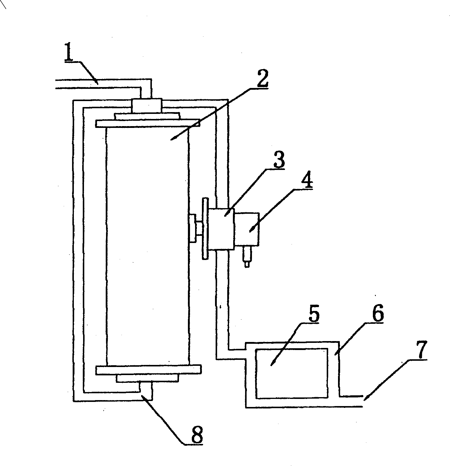
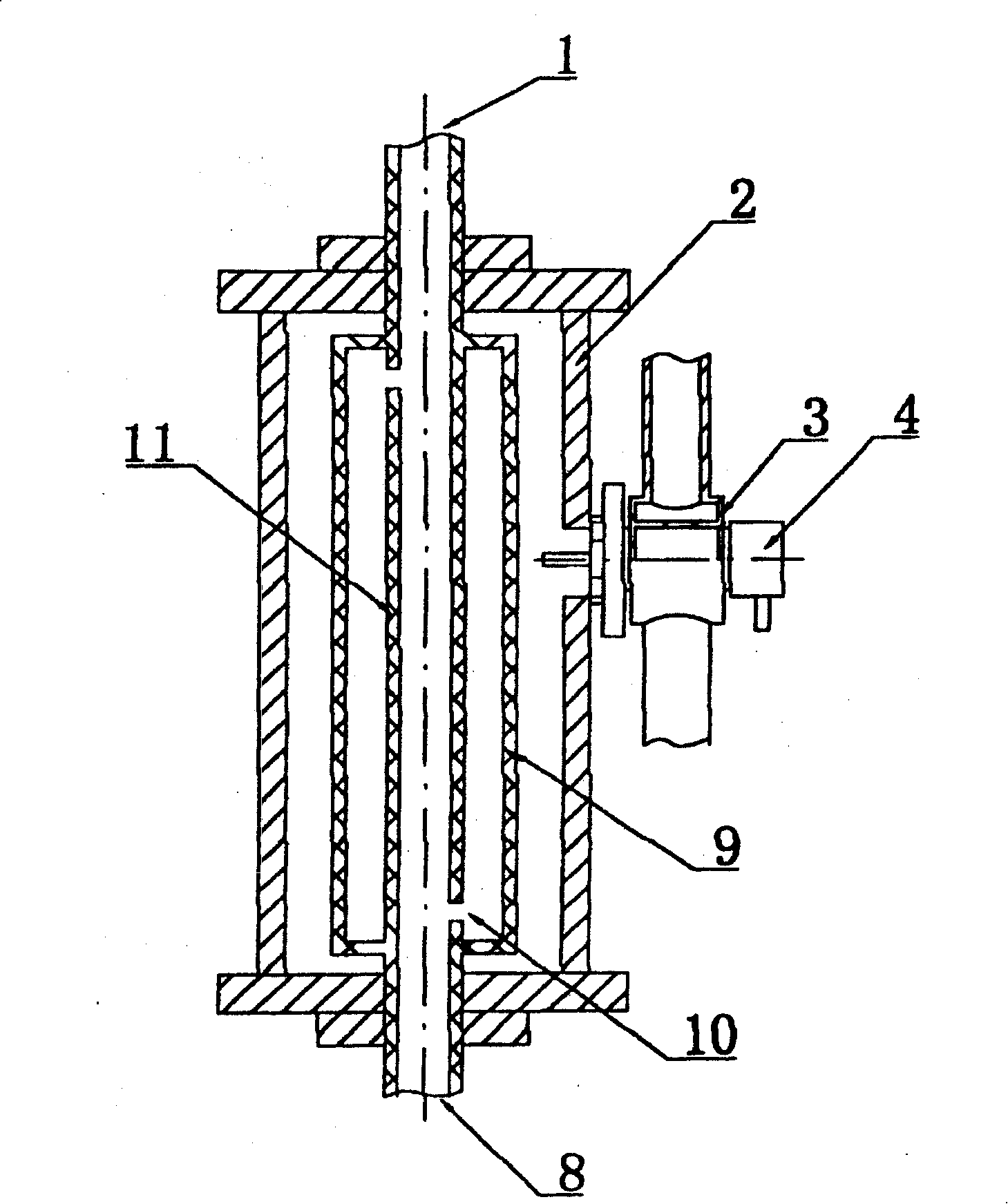
For example, in the design of the application number 00219210.1, the attached figure 2 , attached image 3 As shown, the cooling water jacket 3 and the cooling water jacket 6 are respectively installed on the magnetron 4 and the transformer 5. The purpose of this design is to use the cooling water to achieve the effect of cooling the microwave generating device, so that the magnetron and the power transformer can Continuous work, but after the cooling water jacket 3 on the magnetron 4 and the cooling water jacket 6 on the transformer 5 absorb heat, according to the law of fluid thermodynamics, the heat of the absorbing microwave generating device is easily convected and passed through the water inlet pipe 8 Convection is transferred to the high place, because water is a poor conductor of heat, and the heat absorbed by the cooling water at the highest point of the water inlet pipe 8 is difficult to pass through the highest point of the water inlet pipe 8, along the water inlet pipe 8 to the bottom of the waveguide 2 The lower end of the central water pipe 11 is transferred, and it is easy to directly communicate with the water source by convection to transfer the absorbed waste heat, causing a large amount of heat generated by the magnetron 4 and the power transformer 5 to be directly transferred to the external water source by the cooling water through the water inlet 7 , because the efficiency of the magnetron in the prior art products is generally 57% - 67% into microwave form, the rest of the electric energy is lost in the form of heat, resulting in low thermal efficiency of microwave water heaters, making it difficult for microwave technology to be practically applied
In the design of the application number 02294830.9, the attached Figure 4 Shown, take to be provided with water tank type cooler around microwave tube 5, and add cooling fan 6 to reduce the temperature of microwave tube, because microwave tube 5 is provided with water tank type cooler around and is arranged on the hot water chamber 8 In the uppermost part, a large amount of heat generated when the microwave tube is working is directly transferred to the water in the water jacket of the water tank cooler provided around the microwave tube 5. Since water is a poor conductor of heat, in the cooling water jacket on the upper part of the hot water chamber 8 After the water is heated, it is difficult to convect with the cold water in the lower preheating chamber 9, because according to the law of liquid convection, convection can occur when the lower part of the liquid is heated. In this design, water tank cooling is adopted The device lowers the temperature of the magnetron, because the microwave tube 5 is provided with a water tank type cooler and is arranged on the top of the hot water chamber 8, it is difficult to realize the rapid transmission of a large amount of heat generated by the microwave tube 5 continuous work, resulting in a water tank type cooler. The temperature of the water in the cooler is too high, so it is difficult to ensure the effect of cooling the microwave tube 5. Although the cooling fan 6 is used to cool down, a large amount of waste heat is lost, and the electric heating efficiency is low, which makes it difficult for the microwave technology to be practically applied.

