
Digital fixed frequency anti-interference circuit

A fixed frequency, digital technology, used in electrical components, electronic switches, output power conversion devices, etc., can solve problems such as radio frequency and conduction interference, damage to the main power tube, adjustment signal interference, etc., to eliminate high-frequency interference, The effect of prolonging the service life and convenient debugging

Inactive Publication Date: 2008-07-30
HANGZHOU SINOCOM HIGH TECH
View PDF3 Cites 0 Cited by
  • Summary
  • Abstract
  • Description
  • Claims
  • Application Information

AI Technical Summary

Problems solved by technology

[0002] In power electronic devices, due to the switching of power devices, it will cause strong radio frequency and conduction interference, which will affect the work of the control circuit in severe cases, making it unable to work normally
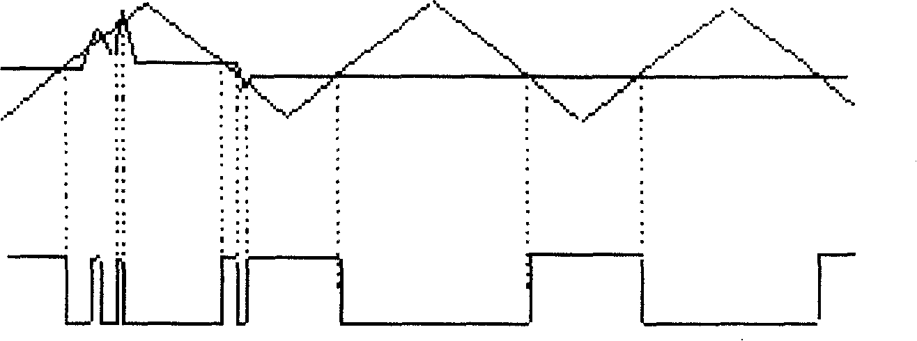
Especially in high-frequency power conversion devices, a situation that is more likely to occur is that the adjustment signal is susceptible to interference from the main switching device at the moment of turning on or off. Multiple switching of power devices in one cycle (such as figure 1 Shown), so that the switching frequency increases, the loss increases, the mild case will cause the deterioration of the control performance, and the severe case will cause the damage of the main power tube

Method used


Image

  • Digital fixed frequency anti-interference circuit
  • Digital fixed frequency anti-interference circuit
  • Digital fixed frequency anti-interference circuit

Examples


Embodiment Construction

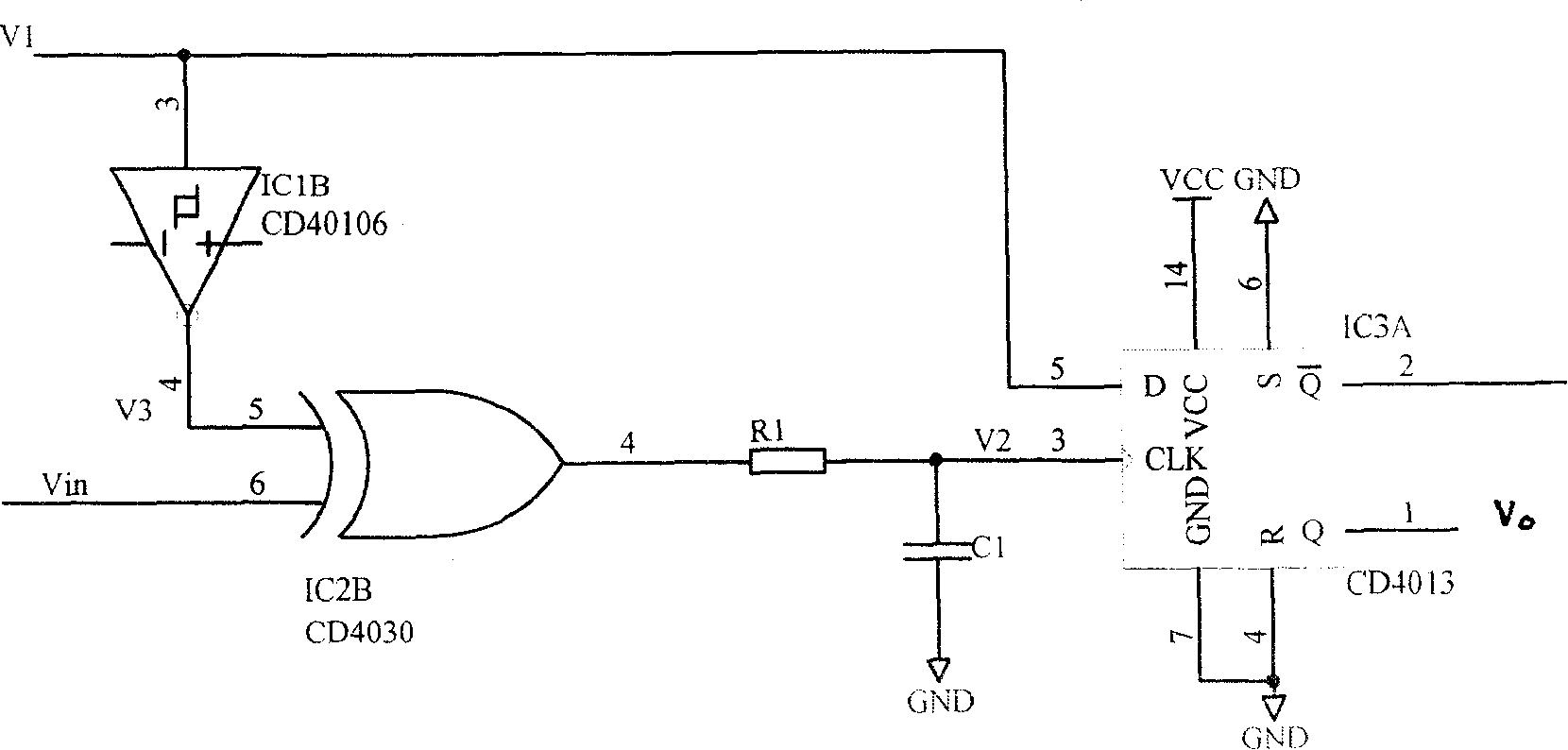
[0014] The circuit structure of this embodiment is as figure 2 As shown, it includes:

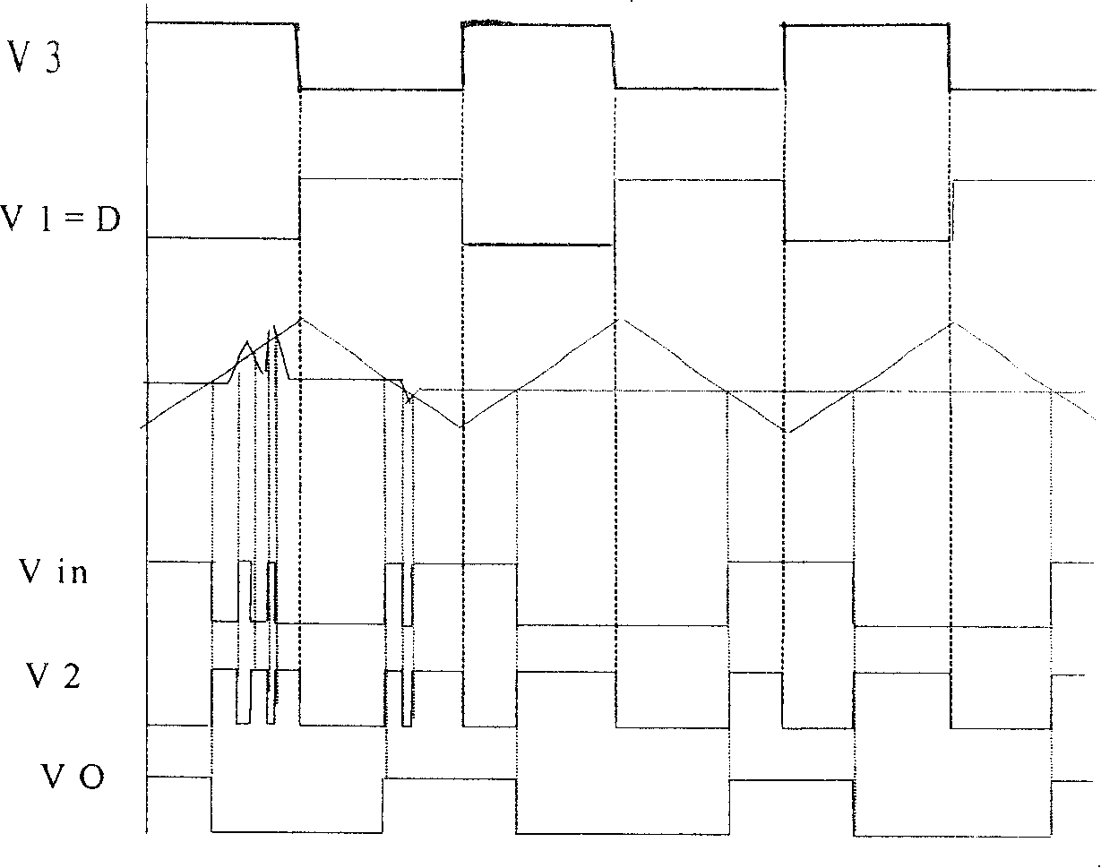
[0015] An inverter IC1B (model: CD40106), which is used to invert the waveform, and its input terminal inputs the reference square wave V which generates the triangular wave carrier signal. 1 , the inverted output signal V 3 (also a square wave) is sent to an input of the XOR gate, and at the same time, the reference square wave V 1 The other way is directly input to the input terminal D of the double D flip-flop, see image 3 The waveform diagram shown.

[0016] An XOR gate IC2B (model: CD4030), used to compare the V at the input 3 and PWM control signal Vin with glitches, see image 3 , if the input signal V 3 Inconsistent with the Vin level (a high level, a low level), the output signal V 2 High level, sent to the clock pin CLK of the double D flip-flop; if the input V 1 Consistent with Vin (all high or all low), the output signal V 2 It is low level and sent to the clock pin C...


PUM


Abstract

This invention relates to a digital anti-interference circuit with fixed frequency including: a phase reverser used in reversing waveforms, the input of which is connected with a primary square V1 generating triangle carrier signals, the output signal V3 is sent to an input pin of a double-input exclusive-OR gate and V1 is connected to the input end of a two-D trigger, an exclusive-OR gate used in comparing the input end through th reversed primary square V3 and PWM control signal Vin with burrs, the output signal V2 is sent to the CLK of the two-D trigger, a double D trigger for shaping the burr PWM control signals so as to output smooth waveforms Vo.

Description

technical field [0001] The invention relates to an anti-jamming circuit, in particular to a digital fixed-frequency anti-jamming circuit. It is suitable for power electronic conversion circuits. Background technique [0002] In power electronic devices, due to the switching of power devices, it will cause strong radio frequency and conduction interference, which will affect the work of the control circuit in severe cases, making it unable to work normally. Especially in high-frequency power conversion devices, a situation that is more likely to occur is that the adjustment signal is susceptible to interference from the main switching device at the moment of turning on or off. Multiple switching of power devices in one cycle (such as figure 1 Shown), so that the switching frequency increases, the loss increases, the mild ones cause the deterioration of the control performance, and the severe ones cause the damage of the main power tube. Contents of the invention [0003]...

Claims


Application Information

Patent Timeline
Patent Type & Authority Patents(China)
IPC IPC(8): H02M1/00H02M1/08H03K17/00H03K17/16
Inventor 周永忠付锋锋金新伟徐传严辉强李常龙
Owner HANGZHOU SINOCOM HIGH TECH
Learn More