Correcting method, correcting circuit and relatively direct conversion receiver

A correction method and correction circuit technology, applied in electrical components, modulation transfer, transmission systems, etc., can solve problems such as large power consumption, and achieve the effect of suppressing second harmonic distortion

Inactive Publication Date: 2008-10-15
MEDIATEK INC
View PDF4 Cites 0 Cited by
  • Summary
  • Abstract
  • Description
  • Claims
  • Application Information

AI Technical Summary

Problems solved by technology

However, the power detector is connected to a directional coupler, and since it operates at a high frequency, the power consumption will be large

Method used


Image

  • Correcting method, correcting circuit and relatively direct conversion receiver
  • Correcting method, correcting circuit and relatively direct conversion receiver
  • Correcting method, correcting circuit and relatively direct conversion receiver

Examples


Embodiment Construction

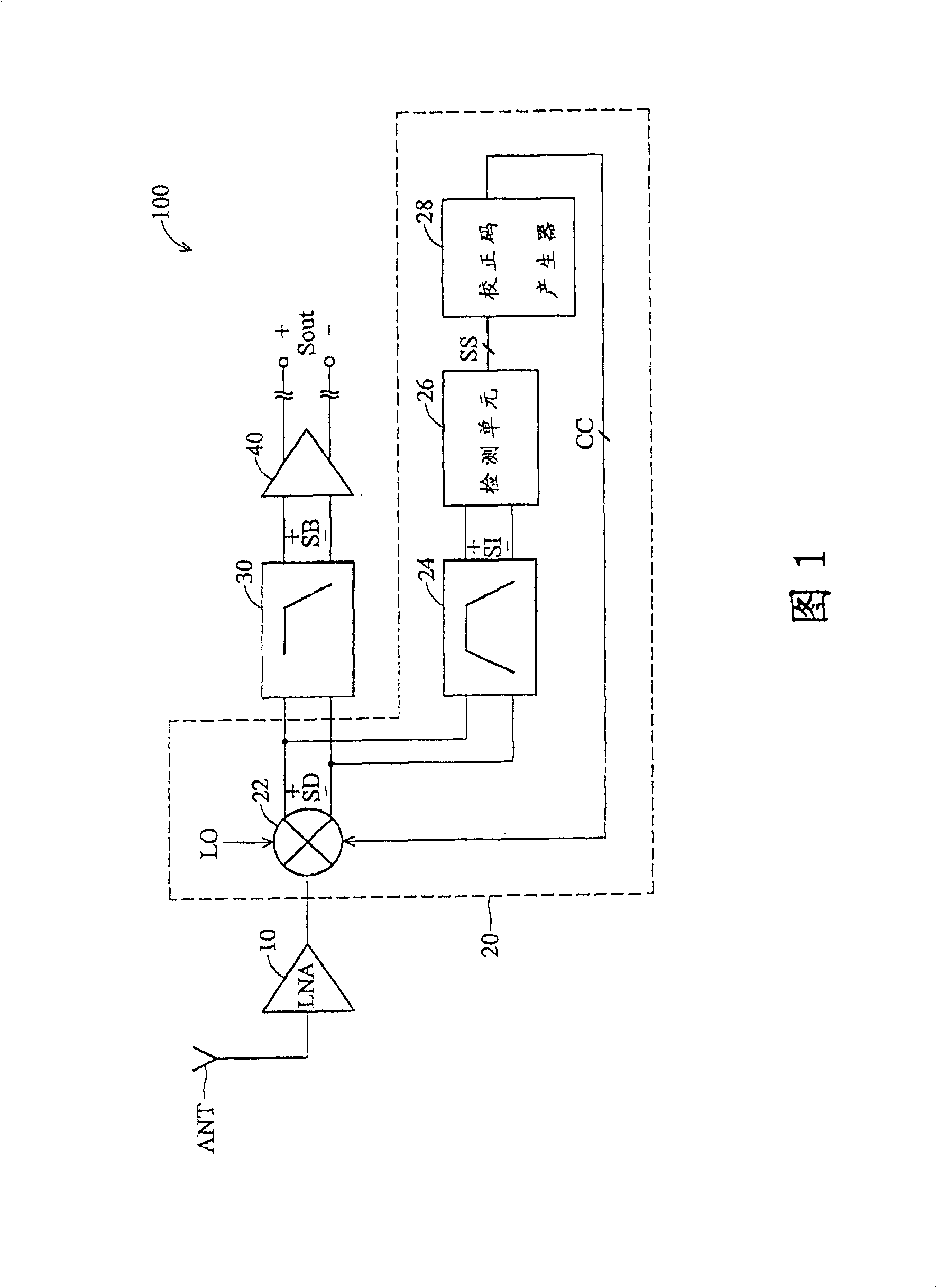
[0056] FIG. 1 shows an embodiment of a direct conversion receiver suitable for suppressing second-order distortion. Specifically, the direct converter receiver (DCR) 100 includes a correction circuit 20 for suppressing two subharmonic distortion.

[0057]As shown in the figure, the direct conversion receiver 100 includes an antenna ANT, a low noise amplifier 10 , a correction circuit 20 , a low pass filter 30 and an amplifier 40 . The radio frequency (RF) signal is sent to the correction circuit 20 through the antenna ANT and the low noise amplifier 10 . The correction circuit 20 is coupled to the output end of the low noise amplifier 10, and includes a down-converter 22 for down-converting the received radio frequency signal into a down-converted signal SD, and generates a down-converted signal SD according to the down-converted signal SD. Correction codes to suppress second harmonic distortion in direct conversion receivers. The down-frequency signal SD generated by the d...


PUM


Abstract

Calibration methods and circuits for suppressing second order distortion in a direct conversion receiver. In the calibration method, a signal output by a down converter is filtered to obtain an interference signal, and strength of the interference signal is detected. A calibration code is obtained according to the detected strength of the interference signal, and the down converter is adapted according to the calibration code to suppress second order distortion.

Description

technical field [0001] The present invention relates to a direct conversion receiver (direct converter receiver; DCR), in particular to a correction method for suppressing second-order dis-tortion (second-order dis-tortion) of the direct conversion receiver, a correction circuit and its related direct conversion receivers. Background technique [0002] In a direct conversion receiver (DCR), there is no need to set an intermediate frequency stage, and the RF signal will be directly converted into a baseband signal. Therefore, a direct conversion receiver will have a lower number of mid-high frequency components than a conventional receiver with an IF stage and, due to its lower complexity, a higher degree of integration than a conventional receiver with an IF stage . [0003] However, techniques that implement direct-conversion receivers tend to have less dynamic range than conventional receivers that include an IF stage. In addition to the dynamic range of a direct-conver...

Claims


Application Information

Patent Timeline
Patent Type & Authority Patents(China)
IPC IPC(8): H04B1/10H03D7/00H04B1/26
CPCH04B1/109H04B1/30
Inventor 屈庆勋王守琮
Owner MEDIATEK INC
Why Eureka
Try Eureka