Method for operation of fast running knitting machine

A technology of knitting machines and driving devices, applied in knitting, weft knitting, warp knitting, etc., can solve the problems of complex and expensive machines, and achieve the effects of improving resolution, fast implementation, and simplifying data transmission

Inactive Publication Date: 2008-11-05
KARL MAYER TEXTILMASCHFAB GMBH
View PDF6 Cites 0 Cited by
  • Summary
  • Abstract
  • Description
  • Claims
  • Application Information

AI Technical Summary

Problems solved by technology

Although such a large amount of data can be handled by the mechanisms ava

Method used


Image

  • Method for operation of fast running knitting machine

Examples


Example Embodiment

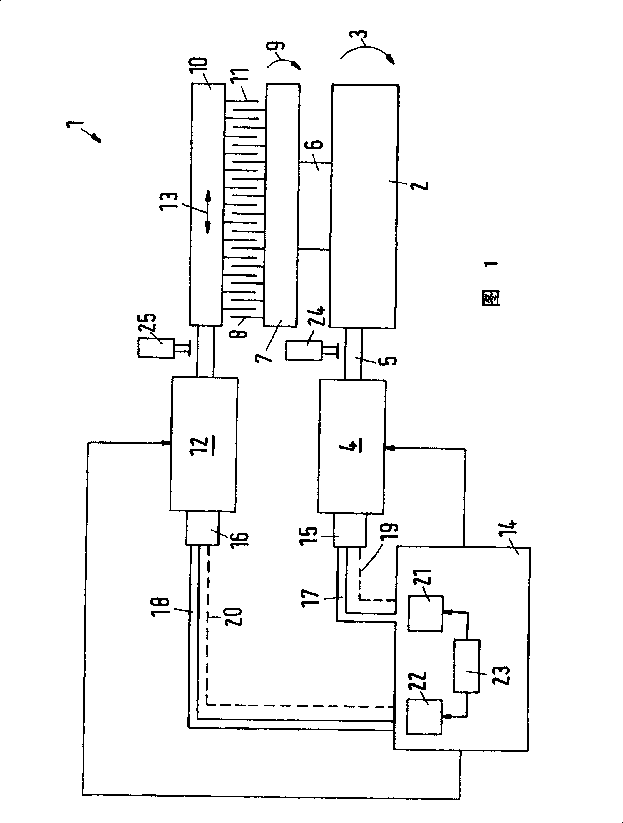
[0021] The chain knitting machine 1 has a spindle 2 which is rotatably driven in the direction of the arrow 3 . In order to generate the rotational movement, the main shaft 2 is provided with a drive 4 , for example an electric motor, which is connected to the main shaft 2 via a clutch 5 .

[0022] The main shaft 2 is connected to a working needle bed 7 via a coupling section 6 , which is only shown schematically. Working needles The needle mattress carries a number of working needles 8 and is deflected back and forth in the direction of the double arrow 9 .

[0023] The bar 10 has a number of needles 11 which, in the case shown, are located in the needle seam between the working needles 8 . The bar 10 is connected to a drive 12 which reciprocates the bar 10 laterally in the direction of the double arrow 13 . Now, during operation, the movement of the working needles 8 (deflective movement) and the movement of the card needles 11 (linear movement) are made to coincide with e...


PUM


Abstract

Provided is an operating method of a rapid travelling loom is capable of improving control motion of a moved part. A rapid travelling loom contains at least one of driving parts. An absolute position of the driving part is detected by an absolute-value providing part. The absolute position is delivered to a controlling part. Increment of a position of the driving part is detected when operating velocity is exceeded. Increment value of the driving part is estimated when the driving part is moved.

Description

technical field [0001] The invention relates to a method of operating a fast-running knitting machine with at least one drive, wherein the absolute position of the drive is determined by means of an absolute value sensor and transmitted to a control device. Background technique [0002] In the following, the present invention is explained by taking a chain knitting machine as an example. In chain knitting machines, different workpieces, such as working needles, comb needles, sheets, etc., work together. Each work piece is fixed on the needle bed in groups. Knitwear is produced by controlling the movement of needle mattresses. In earlier times, the movements of the individual workpieces were mechanically coupled to each other. The central drive is used in all workpieces via the main shaft of the chain knitting machine. In order to connect these workpieces, relatively complex transmissions are therefore sometimes required. These transmissions limit the use of standard str...

Claims


Application Information

Patent Timeline
IPC IPC(8): D04B15/99D04B27/00D04B27/08D04B27/22D04B27/26
CPCD04B27/08D04B27/26D04B27/00D04B27/22
Inventor E·克佩尔特J·福克尔特H·罗尔
Owner KARL MAYER TEXTILMASCHFAB GMBH
Why Eureka
Try Eureka