A separating method for sound field

A separation method and sound field technology, applied in the field of noise, can solve problems such as errors and large separation errors

Inactive Publication Date: 2008-12-10
HEFEI UNIV OF TECH
View PDF7 Cites 0 Cited by
  • Summary
  • Abstract
  • Description
  • Claims
  • Application Information

AI Technical Summary

Problems solved by technology

However, this method has its inherent defects: on the one hand, the shape of the measurement surface is limited, that is, it can only be a regular shape such as a plane, cylinder, or sphere; on the other hand, it is affected by the FFT algorithm, and the separation error is large, especially in the The error is especially obvious when there is a large difference in sound pressure from both sides of the measurement surface

Method used


Image

  • A separating method for sound field
  • A separating method for sound field
  • A separating method for sound field

Examples


Embodiment Construction

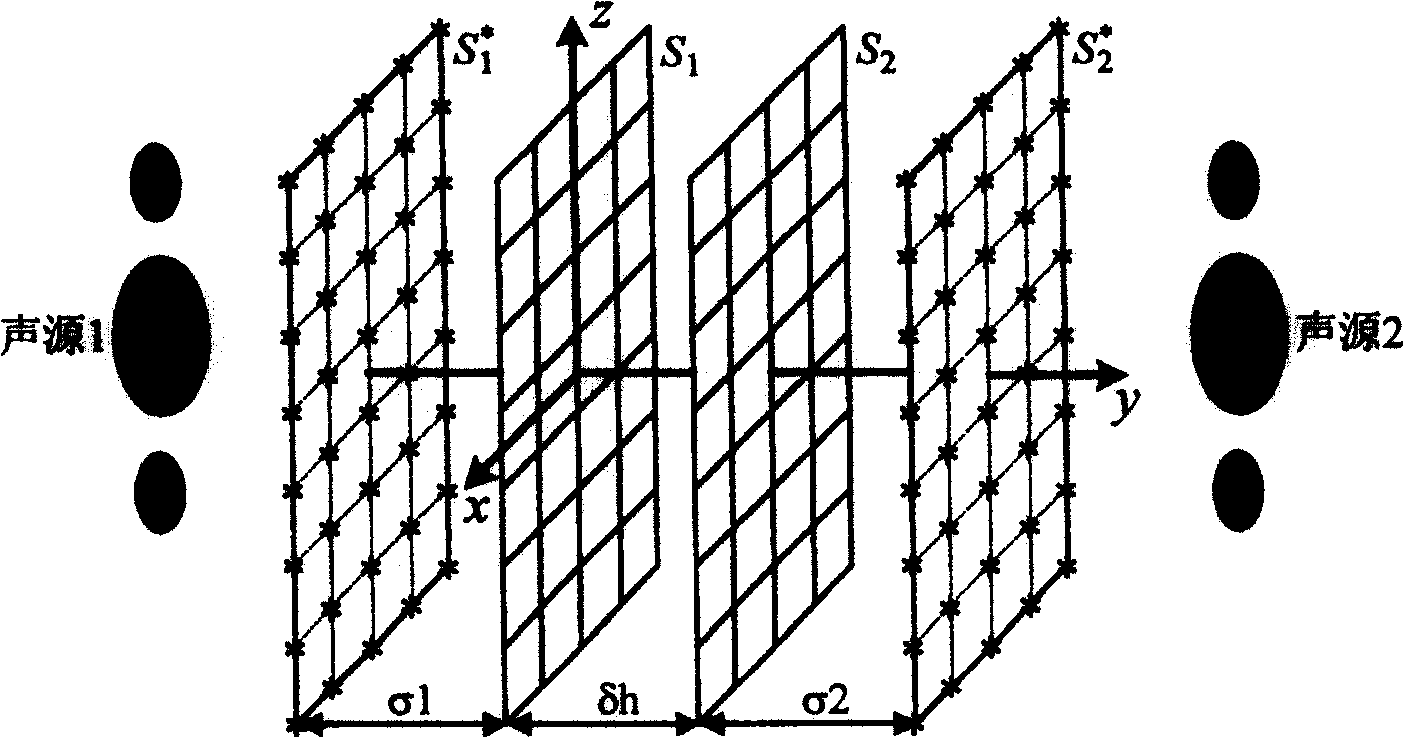
[0107] see figure 2 , in this embodiment, sound sources are distributed on both sides of the measurement surface, wherein sound source 1 is the main sound source, and sound source 2 is a noise source or a reflection or scattering source. In the measured sound field composed of sound source 1 and sound source 2 , there is a measurement surface S between sound source 1 and sound source 2 1 , on the measurement surface S 1 Set between the sound source 2 and the measurement surface S 1 Auxiliary measuring surface S parallel and separated by a distance of δh 2 ; Measuring grid points are respectively distributed on the two measuring surfaces, and the distance between adjacent grid points is less than half a wavelength; δh value is not zero, and is not greater than the minimum interval of measuring grid points.

[0108] The specific implementation steps are:

[0109] a. Use single or multiple microphones to scan on the two measurement surfaces respectively, use a microphone arr...


PUM


Abstract

A method of acoustic field separation is disclosed that characterized in that a detecting surface S1 and a auxiliary detecting surface S2 which is parallel with the detecting surface and spaced with the detecting surface by deltah are set in the acoustic field to be detected; The acoustic pressures of the two surfaces are tested; a void source surface S1* and S2* are set, the equivalent sources are spread in the void source surface; the transitive relationship between the equivalent sources and the acoustic pressures of the two surfaces is built; the separation of radiation sound pressure with acoustic sources of the two sides in detecting surface based on the transitive relationship. The measuring surfaces in the invention can be random geometry which contains flat surface, cylindrical surface or spherical surface; the equivalent source method is the sound field separation algorithm, computational stability is well, computational accuracy is high, accomplishment is simple, and the invention can be widely used in the near acoustic field holographic detection of inner acoustic field or in noise environment, the measuring of material reflection coefficient, the separation of scattered acoustic field.

Description

Technical field: [0001] The invention relates to a sound field separation method in the field of noise in the specialty of physics. Background technique: [0002] In actual measurement, it is usually encountered that there are sound sources on both sides of the measurement surface, or there is reflection or scattering on one side of the measurement surface. In actual engineering, in order to more accurately study the sound radiation characteristics of the actual sound source or the reflection characteristics of the reflective surface, it is necessary to separate the radiated sound from both sides of the measurement surface. In 1980, G.V.Frisk et al. proposed for the first time to use the spatial FFT method to achieve separation and indirectly measure the reflection coefficient of the ocean floor. The advantage of this method is that it does not need to predict the intensity and position information of the sound source. In 1980, G.Weinreich et al proposed to use two methods ...

Claims


Application Information

Patent Timeline
Patent Type & Authority Patents(China)
IPC IPC(8): G01H17/00G01N29/00
Inventor 毕传兴陈心昭陈剑
Owner HEFEI UNIV OF TECH
Why Eureka
Try Eureka