Encoder

An encoder and circumference technology, applied in the field of encoders, can solve problems such as complex shapes and high prices

Inactive Publication Date: 2009-01-07
NOK CORP
View PDF13 Cites 0 Cited by
  • Summary
  • Abstract
  • Description
  • Claims
  • Application Information

AI Technical Summary

Problems solved by technology

[0003] However, in the past, in order to form the above-mentioned unequal-pitch portion 54 on the encoder 51, the encoder 51 was manufactured using a special-shaped magnetized head having an unequal-pitch portion on a part of the circumference of the magnetic imparting portion. The magnetized head is dedicated. There is thus the inconvenience of having to make a magnetized head corresponding to the item of each encoder 51
The special shape of the above-mentioned magnetized head with unequal pitch parts, the shape is complicated and the price is high
[0004] And, as another conventional technology among the present invention, the following encoder is disclosed in the following patent document 1: it is formed by at least one band-shaped magnetized body pasted along its circumferential direction by a ring-shaped supporting member, and At least one place on the circumference of the reference position signal is formed with a detected portion for the reference position signal, the magnetic poles of the opposite end portions of the magnetized body become the same pole, and a gap is formed at the opposite portion of the magnetized body , to detect a reference position signal with a small bottom value in the peak value of the output signal, but the prior art disclosed in this publication does not change the fact that it is necessary to use a magnetized head with a special shape with unequal pitch portions

Method used


Image

  • Encoder
  • Encoder
  • Encoder

Examples


Embodiment

[0020] Next, embodiments of the present invention will be described based on the drawings.

no. 1 example

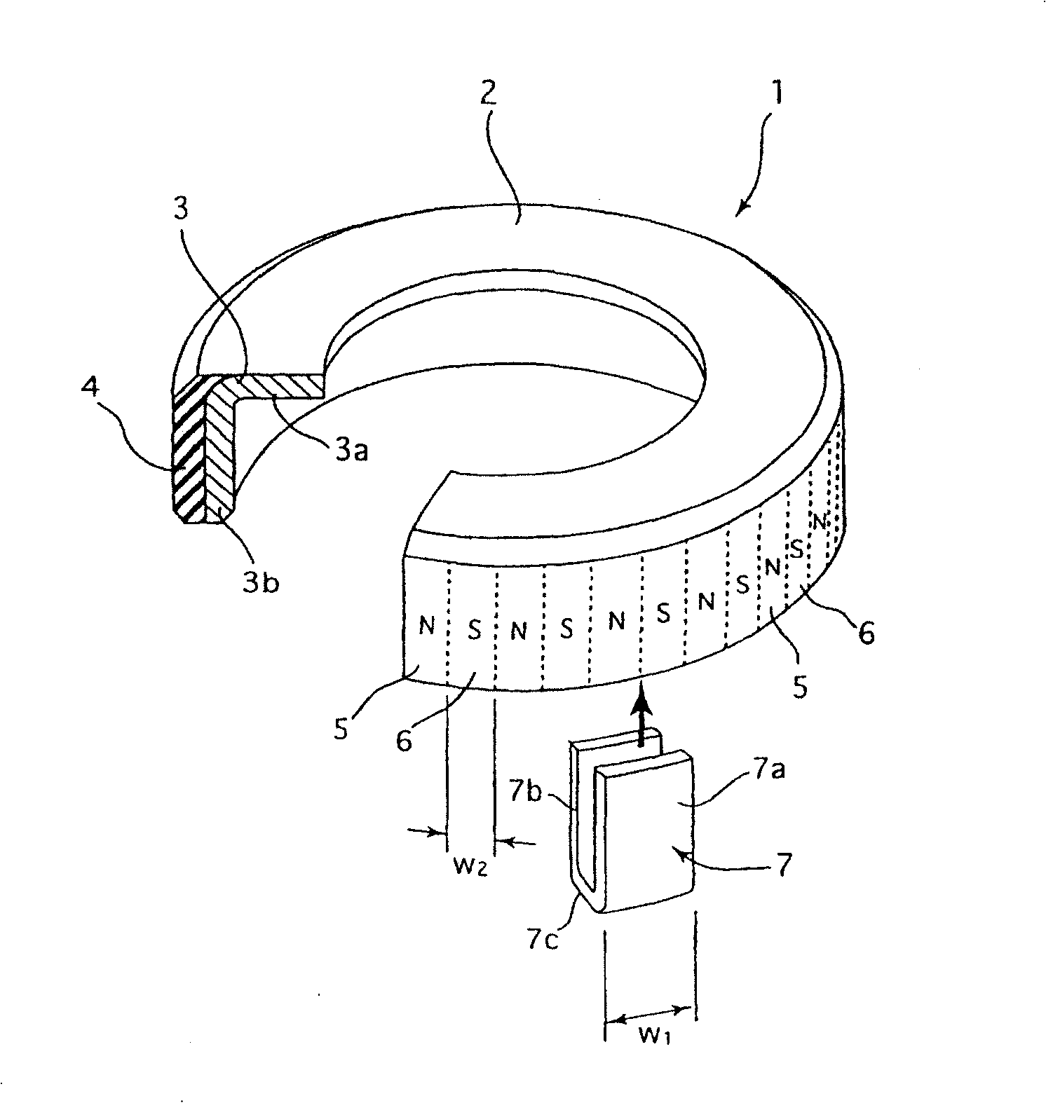
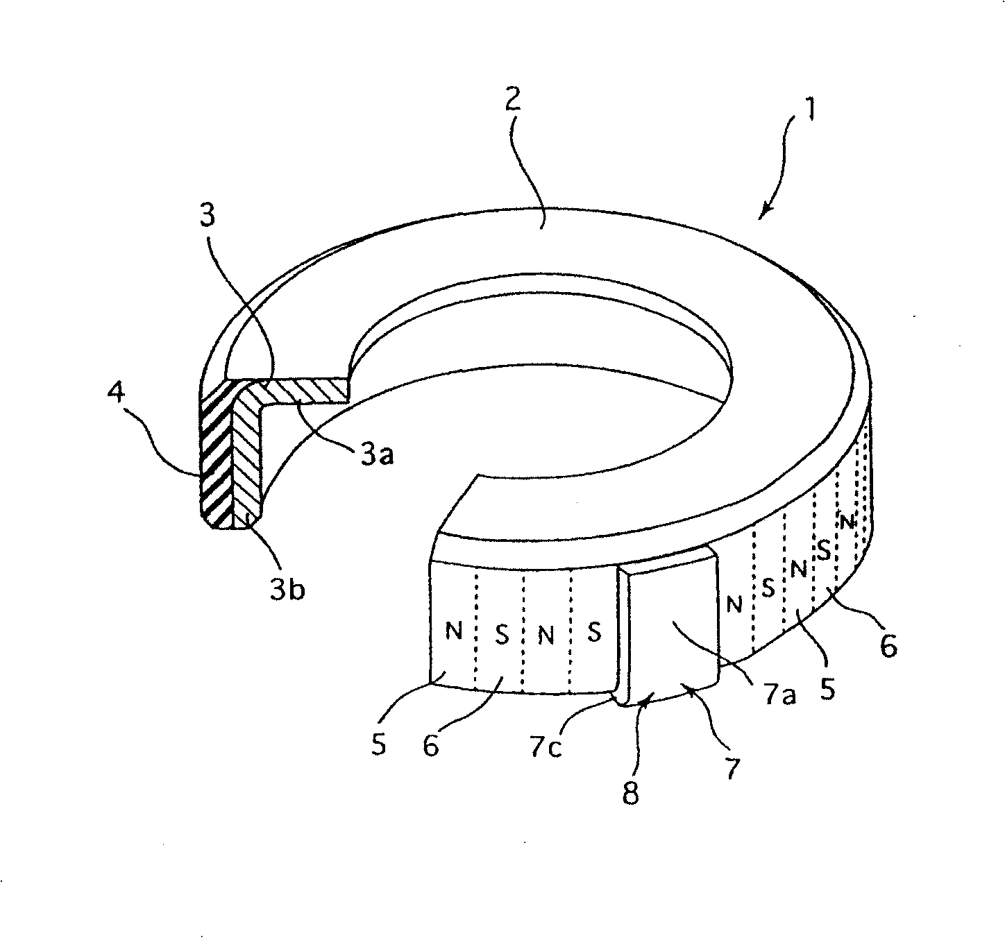
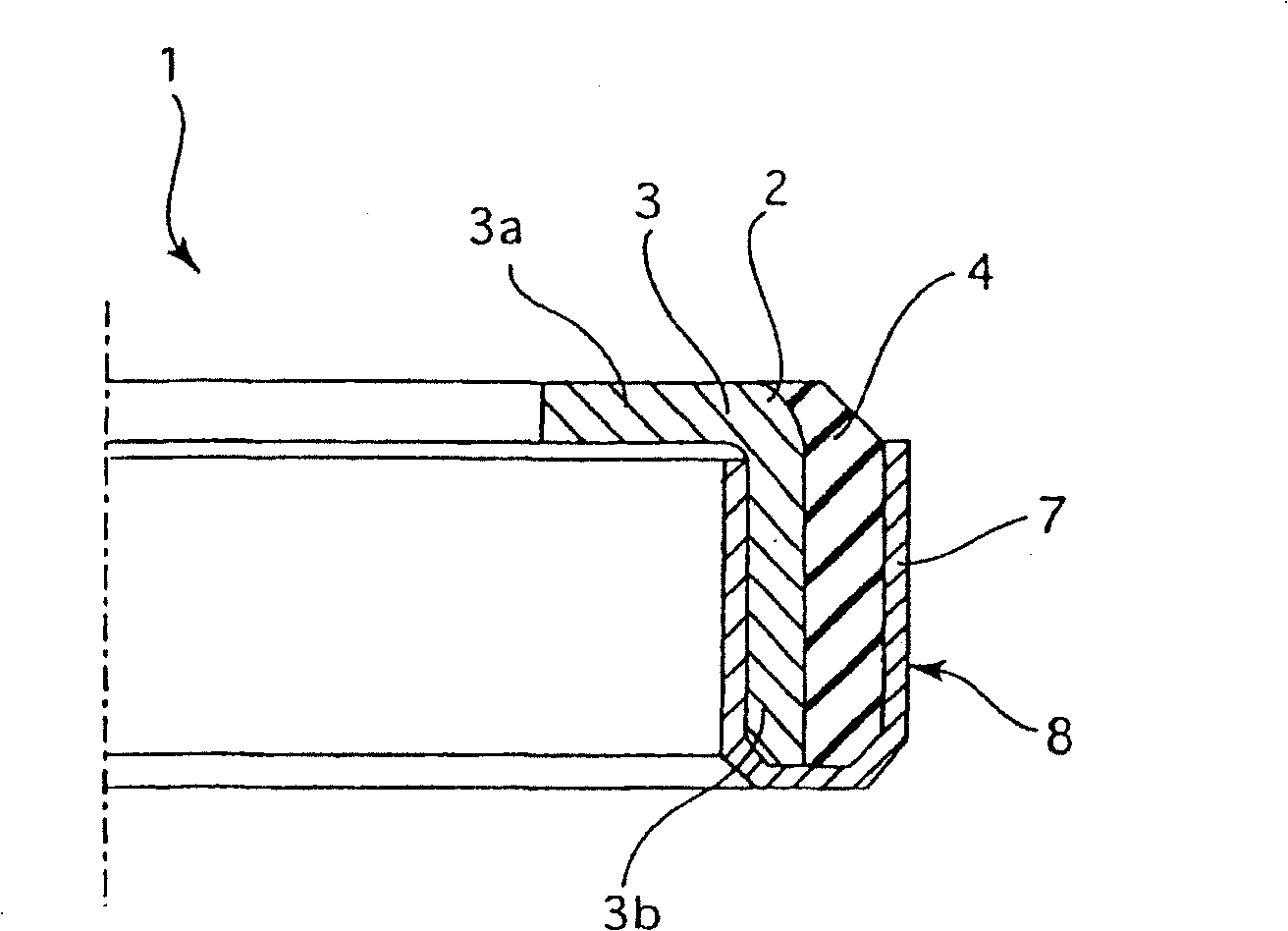
Figure 1 to Figure 3 represents an encoder 1 of a first embodiment of the invention, figure 1 is a partially cutaway perspective view showing the manufacturing process of the above-mentioned encoder 1; figure 2 is a partially cutaway perspective view showing the completed state of the above-mentioned encoder 1; image 3 It is a half cross-sectional view showing the encoder 1 described above.

[0022] like figure 2 As shown, in the encoder 1 of this embodiment, the N poles 5 and S poles 6 of the magnets are alternately arranged at equal intervals in the circumferential direction, and a part of the circumference is provided with unequal intervals 8, such as figure 1 As shown, it includes an encoder main body 2 that arranges N poles 5 and S poles 6 at equal intervals across the entire circumference, and a magnetic shielding body 7 that is installed on a part of the circumference of the above-mentioned encoder main body 2 to shield this part. A shielding body 7 is installe...


PUM


Abstract

In an encoder (1), in which N-poles (5) and S-poles (6) of magnets are arranged alternately in a circumferential direction and in which an unequal pitch portion (8) is provided in a part on a the circumference, it is aimed that the encoder (1) having the unequal pitch portion (8) can be easily manufactured without using a magnetizing head of a special shape having an unequal pitch portion. The unequal pitch portion (8) is formed by arranging the N-poles (5) and the S-poles (6) at an equal pitch all over the circumference and then providing a part on the circumference with a shielding member (7) for shielding a magnetism. Furthermore, the unequal pitch portion (8) is formed by arranging the N-poles (5) and the S-poles (6) at an equal pitch all over the circumference and then providing a part on the circumference with a cut portion.

Description

technical field [0001] The present invention relates to an encoder used in combination with a magnetic sensor to detect the rotational speed, rotation angle, etc. of a rotating member such as a rotating shaft. Background technique [0002] In the past, such as Figure 5 As shown, there is known an encoder 51 in which N poles 52 and S poles 53 of magnets are alternately arranged at equal intervals in the circumferential direction. Its rotation position is specially designated, and a part of the circumference is set as an unequal-spaced portion 54 of the reference point on the circumference. [0003] However, in the past, in order to form the above-mentioned unequal-pitch portion 54 on the encoder 51, the encoder 51 was manufactured using a special-shaped magnetized head having an unequal-pitch portion on a part of the circumference of the magnetic imparting portion. The magnetized head is dedicated. Therefore, there is an inconvenience that it is necessary to manufacture a m...

Claims


Application Information

Patent Timeline
Patent Type & Authority Patents(China)
IPC IPC(8): G01D5/244G01D5/245
CPCG01D5/2457G01D5/145G01D2205/80
Inventor 鎗水健一长泽晋治大野义昭小林直人
Owner NOK CORP
Why Eureka
Try Eureka