Miniature heat-collecting pump

A heat-collecting and miniature technology, applied in the direction of pumps, pump devices, pump components, etc., can solve the problems of rising chip heat, increased leakage current, increased installation and maintenance costs, etc., to improve heat collection capacity, reduce installation space, The effect of enhancing reliability

Inactive Publication Date: 2009-01-21
张炜 +1
View PDF8 Cites 0 Cited by
  • Summary
  • Abstract
  • Description
  • Claims
  • Application Information

AI Technical Summary

Problems solved by technology

[0002] In the past 40 years, the semiconductor industry has developed rapidly following Moore's theorem, and the number of integrated transistors per unit area in a chip has doubled every 18 months; at the same time, in order to meet the growing demand for fast data processing, the computing frequency of general computing chips has also increased significantly ; and as the size of the transistor becomes smaller and smaller, the leakage current will increase significantly, which will lead to a sharp increase in the heat generation inside the chip
It is far from enough to dissipate the heat only by solid radiators (ie: air-cooled radiators), because the heat dissipation efficiency and method limitations of solid radiators can no longer meet the needs of current semiconductor product development.
At present, the general liquid cooling radiator uses a separate heat collector and circulation pump body, which will reduce the heat collection capacity of the entire system and increase the cost of installation and maintenance.

Method used


Image

  • Miniature heat-collecting pump
  • Miniature heat-collecting pump
  • Miniature heat-collecting pump

Examples


example 1

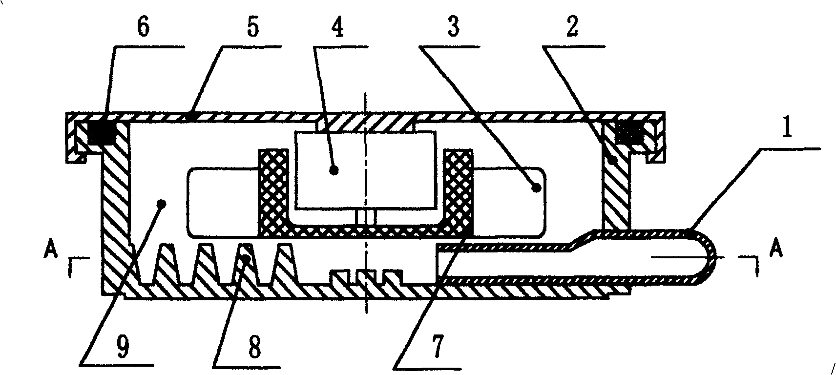
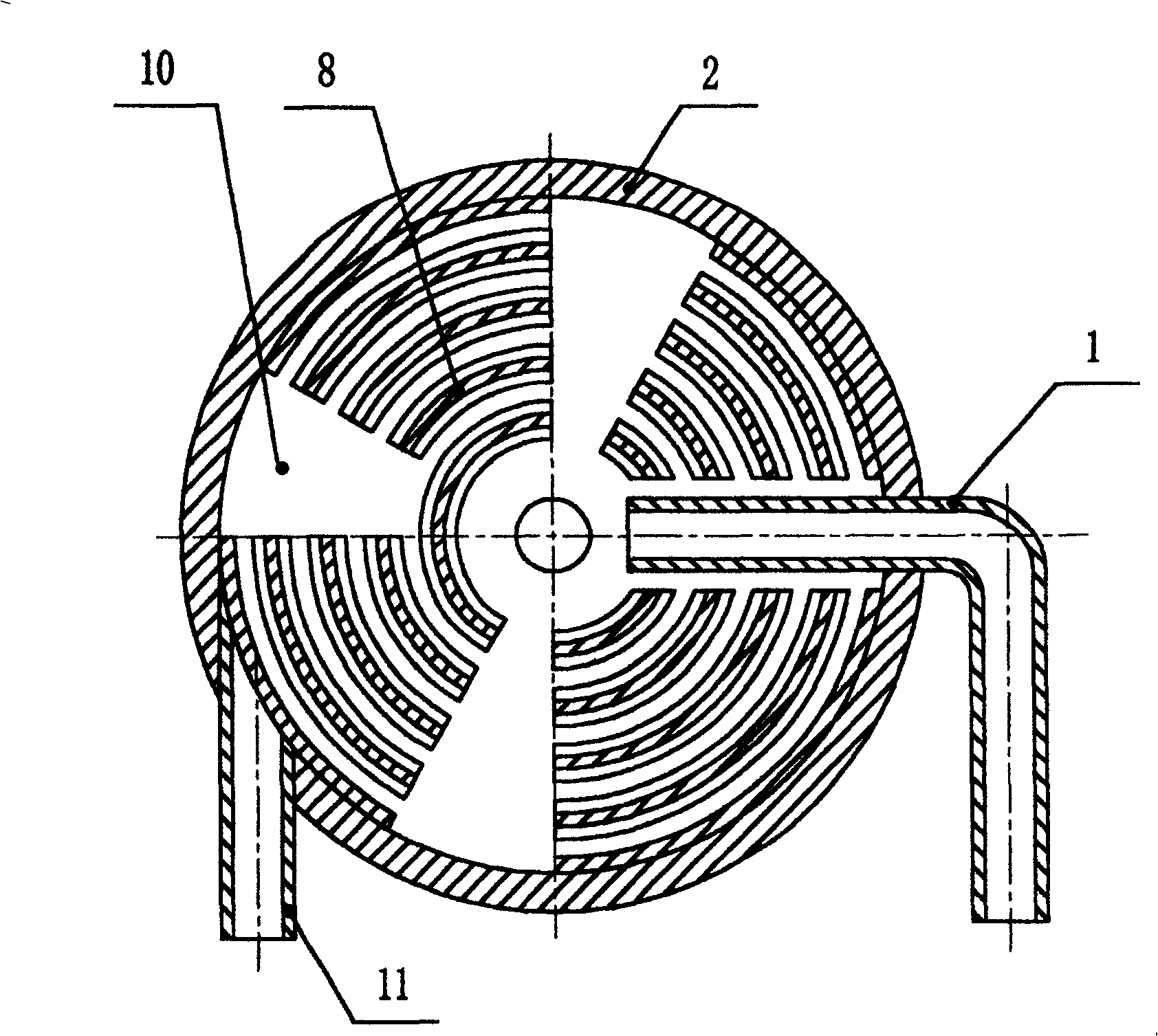
[0029] Such as figure 1 , figure 2 As shown, the micro-collector heat pump includes a water inlet pipe 1, a pump body 2, blades 3, a motor 4, a pump cover 5, a sealing ring 6, an impeller 7, and a water outlet pipe 11, and the pump cover 5 is fixedly connected with the pump body 2. A sealing ring 6 is arranged between the pump cover 5 and the pump body 2, the cavity between the pump cover 5 and the pump body 2 is a water chamber 9, and the pump body 2 is provided with a water inlet pipe 1 and an outlet pipe 11, and the water inlet pipe 1 and the outlet pipe The water pipes 11 communicate with the water chamber 9 respectively. The water inlet pipe 1 is located on the side of the pump body 2 near the bottom, and the outlet of the water inlet pipe 1 is located at the inner middle of the bottom of the pump body; Inside, the motor 4 is fixedly connected to the pump cover 5, and the output of the motor 4 is fixedly connected to the impeller 7. There are four blades 3 on the impell...

example 2

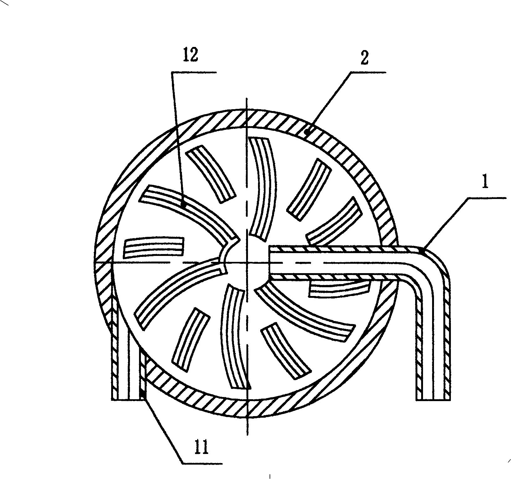
[0031] Such as figure 1 , image 3 As shown, the micro-collector heat pump includes a water inlet pipe 1, a pump body 2, blades 3, a motor 4, a pump cover 5, a sealing ring 6, an impeller 7, and a water outlet pipe 11, and the pump cover 5 is fixedly connected with the pump body 2. A sealing ring 6 is arranged between the pump cover 5 and the pump body 2, the cavity between the pump cover 5 and the pump body 2 is a water chamber 9, and the pump body 2 is provided with a water inlet pipe 1 and an outlet pipe 11, and the water inlet pipe 1 and the outlet pipe The water pipes 11 communicate with the water chamber 9 respectively, the water inlet pipe 1 is located at the side of the pump body 2 near the bottom, the outlet of the water inlet pipe is located at the inner middle of the bottom of the pump body; the motor 4, the impeller 7 and the blade 3 are located in the water chamber 9 , the motor 4 is installed on the pump cover 5, the output of the motor 4 is fixedly connected w...


PUM


Abstract

Present invention relates to a heat collection for heat radiation. It includes water inlet pipe, pump body, vane, motor, pump cover, impeller and outlet pipe, wherein the pump cover and pump body fixed joint and whose cavity forming the water jacket space, pump body set with water inlet pipe and let-off pipe respectively communicated with water jacket space, motor, impeller and vane located in water jacket space, motor mounted on pump cover, motor output fixed joint with impeller, impeller set with 2-6 vanes, it featuring bottom inner side surface set with heat radiation fins, pump body bottom outer side surface being plane and close contacted with heat source in using. Said invention has high heat exchange efficiency and small volume property.

Description

technical field [0001] The invention relates to a pump for heat dissipation. Background technique [0002] In the past 40 years, the semiconductor industry has developed rapidly following Moore's theorem, and the number of integrated transistors per unit area in a chip has doubled every 18 months; at the same time, in order to meet the growing demand for fast data processing, the computing frequency of general computing chips has also increased significantly ; And as the volume of the transistor becomes smaller and smaller, the leakage current will increase significantly, causing the heat inside the chip to rise sharply. It is far from enough to dissipate the heat only by solid heat sinks (ie: air-cooled heat sinks), because the heat dissipation efficiency and method limitations of solid heat sinks cannot meet the needs of current semiconductor product development. However, the current general liquid-cooled radiator uses a separate heat collection device and circulation pum...

Claims


Application Information

Patent Timeline
Patent Type & Authority Patents(China)
IPC IPC(8): F04D29/62F04D29/58F04D29/42F04D29/24F04D13/06H05K7/20
Inventor 张炜张炯
Owner 张炜
Why Eureka
Try Eureka