
Contact image scanner with multi focal length and multi resolution

A multi-resolution, contact technology, applied in the fields of instrumentation, image communication, optics, etc., can solve the problems of contact image scanners, such as volume limitation, only palliative treatment, and lack of adjustable scanning focal length and resolution.

Inactive Publication Date: 2009-02-11
CREATIVE SENSOR INC
View PDF5 Cites 0 Cited by
  • Summary
  • Abstract
  • Description
  • Claims
  • Application Information

AI Technical Summary

Problems solved by technology

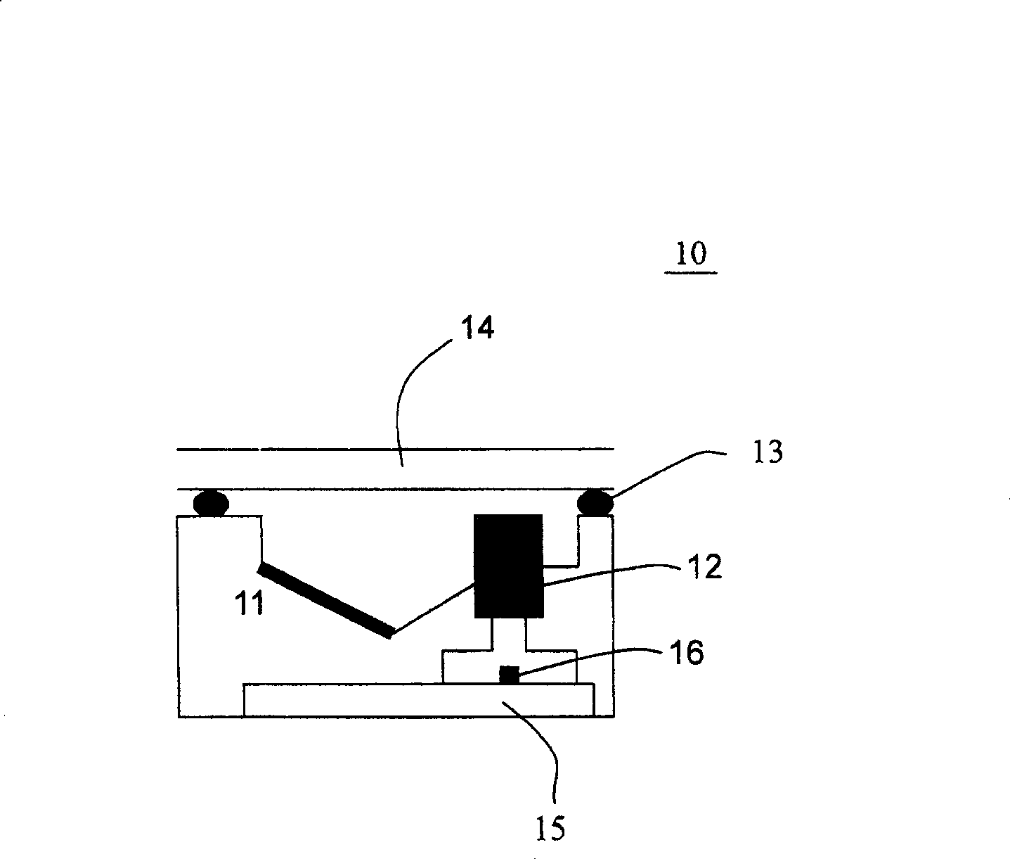
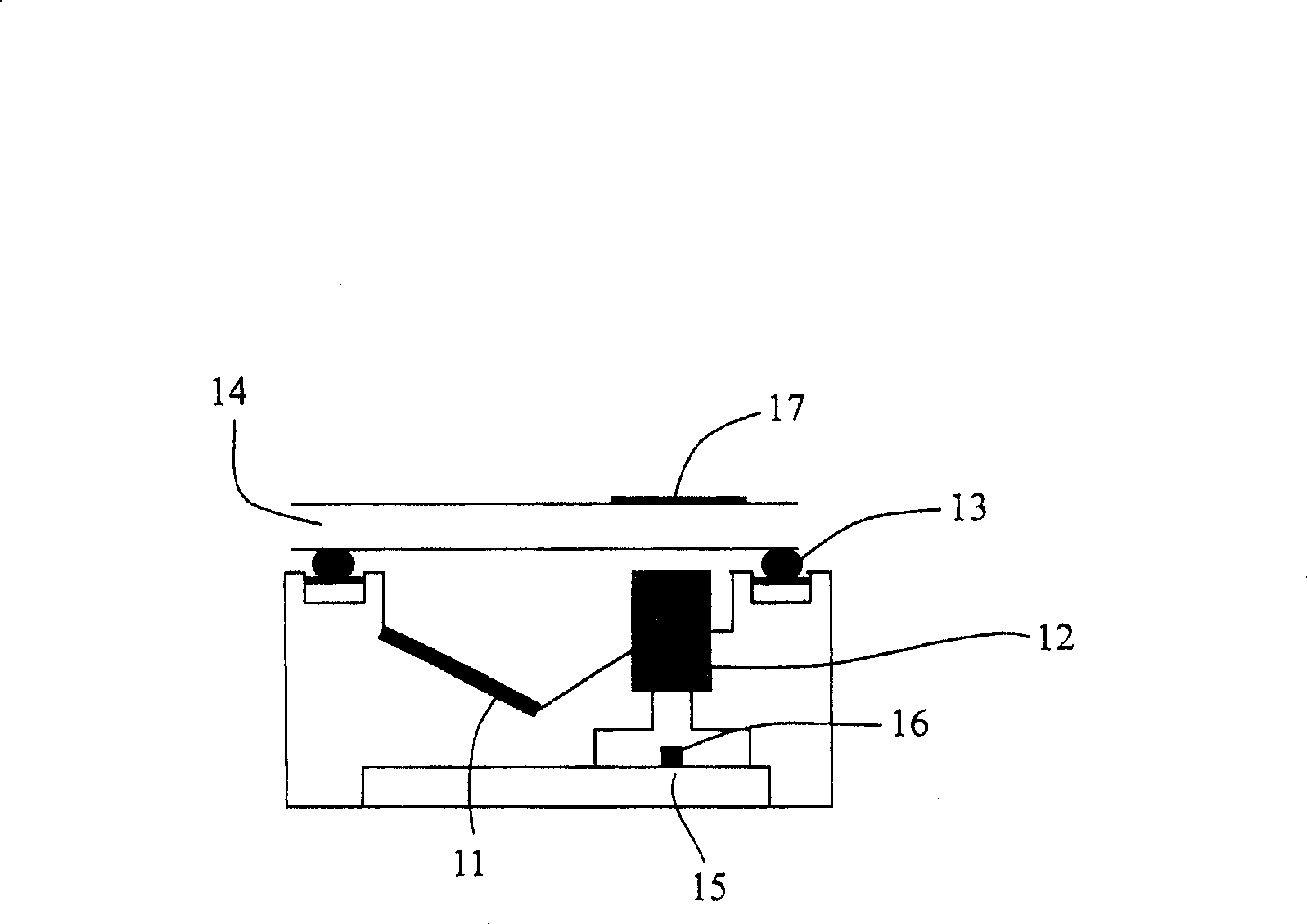
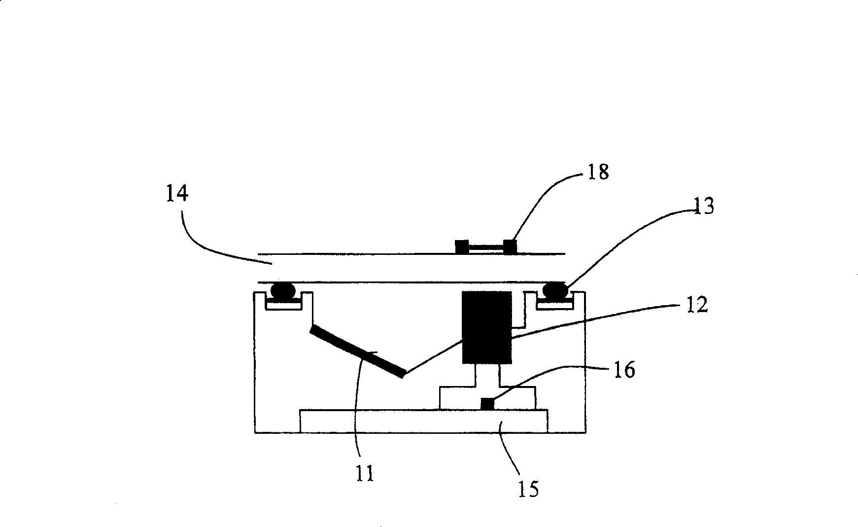
[0013] First, fixing the photosensitive element arrays 26 and 27 arranged in a parallel manner limits the relative position and arrangement of the corresponding lenticular lenses 22 and 23, which in turn restricts the volume of the contact image scanner. The trend of miniaturization is bound to limit the number of lenticular lenses used, which is why this patent is only applicable to two sets of lenticular lenses
[0014] Secondly, since there are only two sets of lenticular lenses and photosensitive element arrays, this patent is quite limited in the applicable range of objects to be scanned, that is, the applicable range of focal lengths of different scanned images of the objects to be scanned 28 and 29 is not enough widely
[0015] Moreover, the relative positions of photosensitive element arrays 26 and 27, lenticular lenses 22 and 23, and circuit board 25 are all fixed. Compared with the prior art, although a different scanning focal length and resolution have been added, in fact the scanning focal length And the resolution is still not adjustable, so it can still only treat the symptoms but not the root cause

Method used


Image

  • Contact image scanner with multi focal length and multi resolution
  • Contact image scanner with multi focal length and multi resolution
  • Contact image scanner with multi focal length and multi resolution

Examples


no. 1 example

[0065] Please refer to FIG. 3( a ), which is a structural diagram of the first embodiment of the contact image scanner with multiple focal lengths and multiple resolutions of the present invention. Wherein, the contact image scanner 30 using contact image sensor (contact image sensor, CIS) technology consists of a first lenticular lens 32, a second lenticular lens 33, a glass 34, a circuit board 35, a first group of photosensitive element arrays 36, and The second group of photosensitive element arrays 37 are jointly packaged in a casing (not shown in the figure).

[0066] In the contact image scanner 30, the first lenticular lens 32 and the second lenticular lens 33 correspond to the first group of photosensitive element arrays 36 and the second group of photosensitive element arrays 37 and are suspended above the two groups of photosensitive element arrays, The glass 34 is suspended above the group of lenticular lenses, and the first group of photosensitive element arrays 36...

no. 2 example

[0074] see Figure 5 , which is a structural diagram of a second embodiment of the contact image scanner with multiple focal lengths and multiple resolutions of the present invention. The only difference from the aforementioned first embodiment is that the first group of photosensitive element arrays 56 and the second group of photosensitive element arrays 57 of this embodiment are respectively located on different first circuit boards 55 and second circuit boards 55', The first circuit board 55 and the second circuit board 55' are connected by connectors 51 and 51'.

[0075] Same as the first embodiment, the second photosensitive element array 57 composed of a plurality of second photosensitive elements can be located at the front end or the tail end of the first photosensitive element array 56 composed of a plurality of first photosensitive elements, as long as the two groups Arrays can be arranged in a single row, such as Figure 4 shown.

[0076] The focal length and res...

no. 3 example

[0081] The structure of the third embodiment of the contact image scanner with multiple focal lengths and multiple resolutions of the present invention is similar to that of the second embodiment, but the only difference is that the first group of photosensitive element arrays 56 and the second Although the groups of photosensitive element arrays 57 are respectively located on different circuit boards, the second group of photosensitive element arrays 57 composed of a plurality of second photosensitive elements and the first group of photosensitive element arrays 56 composed of a plurality of first photosensitive elements are connected to each other. arranged in parallel; as Figure 6 As shown, in addition to the length of the second group of photosensitive element arrays 57 can be made according to the requirements of the object to be scanned, its position relative to the X axis can also be defined according to the designer's preferences, as shown in the figure can be in posit...


PUM


Abstract

The image scanner includes following parts: at least a first circuit board and a second circuit board; at least two sets of sensitizing element array (SEA) composed of first set of SEA and second set of SEA located on the first circuit board and the second circuit board respectively; at least one set of columnar lens composed of first and second columnar lenses; first columnar lens and second columnar lens suspended on the corresponding first set of SEA and second set of SEA; a glass is suspended on the set of columnar lens; adjusting relative position between the first circuit board and the second circuit board makes the two sets of SEA and the set of columnar lens form at least two focuses and resolutions in order to scan different objects to be scanned on the glass.

Description

[0001] This application is a divisional application of a patent application with an application date of August 13, 2004, an application number of 200410056649.1, and an invention titled "Contact Image Scanner with Multi-focal Length and Multi-resolution". technical field [0002] The invention relates to a contact image scanner with multiple focal lengths and multiple resolutions, in particular to a contact image scanner applicable to objects to be scanned with different scanning image focal lengths. Background technique [0003] The working principle of the contact image sensor (contact image sensor, CIS) module is to irradiate the light generated by the light source on the manuscript to be scanned, reflect it through the lens group, and then gather it in the charge-coupled device (CCD) Or after it is received by complementary metal oxide semiconductor (CMOS), this type of photosensitive element is used to convert the light signal into an electrical signal, and then generate...

Claims


Application Information

Patent Timeline
Patent Type & Authority Patents(China)
IPC IPC(8): H04N1/04H04N1/024H04N1/028G02B3/06
Inventor 苏铃达
Owner CREATIVE SENSOR INC
Learn More