Motion controller

A technology of stroke controller and stroke, applied in the direction of using feedback control, using optical devices to transmit sensing components, etc., can solve the problems of high labor intensity, low work efficiency, troublesome maintenance, etc., and achieve maintenance-free, low cost, and control reliable effect

Active Publication Date: 2009-02-18
常州电站辅机股份有限公司
View PDF4 Cites 0 Cited by
  • Summary
  • Abstract
  • Description
  • Claims
  • Application Information

AI Technical Summary

Problems solved by technology

Some of the above-mentioned stroke controllers do not have the power-off memory function, and must use batteries to memorize the stroke, which brings trouble to maintenance; some have low precision, or need to adjust the stroke on the valve of the gate valve or various regulating valves, and the work efficiency is low , Poor environment, high labor intensity

Method used


Image

  • Motion controller
  • Motion controller

Examples


Embodiment Construction

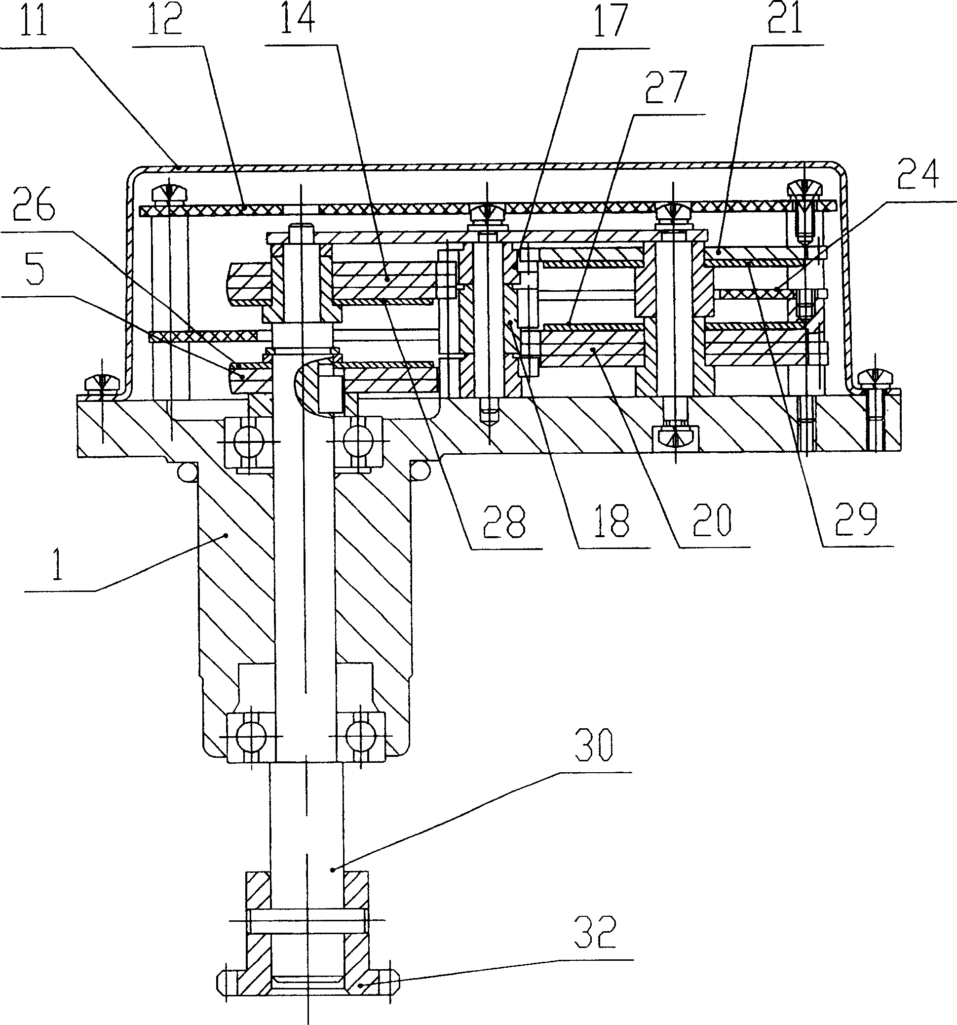
[0012] See figure 1 A stroke controller of the present invention includes a stroke input shaft 30, a stroke input gear 32, a base 1, and a control circuit composed of a photoelectric sensor code taking circuit and a level conversion circuit. The stroke output shaft 30 is fixedly attached to the stroke Input gear 32, bottom counting gear 5, the first to fourth code disc 26 is fixed on the bottom counting gear 5, the gear meshing with the bottom counting gear 5 drives the bottom counting gear 20 to rotate, on the bottom counting gear 20 The 5th to 8th code disc 27 is fixed, and the gear 18 meshing with the bottom counting gear 20 drives the top counting gear 14 to rotate. The 9th to 12th code disc 28 is fixed on the top counting gear 14 to count with the top layer. The gear 17 meshed with the gear 14 drives the top counter gear 21 to rotate, and the 13th to 16th bit code disc 29 is fixed on the top counter gear 21. When the stroke output shaft 30 drives the code disc to rotate, the ...


PUM


Abstract

A controller of stroke consists of stroke input shaft, stroke input gear, base, control circuit formed by code fetching circuit of photoelectric transducer and electric level conversion circuit. Its controlling method is also disclosed.

Description

Technical field [0001] The present invention relates to a stroke controller, in particular to a high-precision stroke control device that adopts the principle of photoelectric conversion and drives gate valves and various regulating valves controlled by a 16-bit absolute code. Background technique [0002] Most of the traditional travel controllers are purely mechanical, adopting the principle of multi-stage counter gear carry, and the last stage gear drives a micro switch or hard contact switch to control. Its structure is complex, volume and mass are relatively large, it can only output the contact signal of the extreme position to the control system outside the machine, and without the output of the intermediate position signal, the intermediate position cannot be controlled. There is also an incremental electronic travel controller, which uses the Hall element to generate pulses to determine the position. The structure is simple and the cost is low. Some of the above-mentione...

Claims


Application Information

Patent Timeline
Patent Type & Authority Patents(China)
IPC IPC(8): G05D3/12G01D5/26
Inventor 焦子靖邵杰葛润平
Owner 常州电站辅机股份有限公司
Why Eureka
Try Eureka