Method for measuring complex foundation sedimentation and deformation by geological radar

A geological radar and foundation settlement technology, applied in the direction of measuring devices, electromagnetic wave detection, radio wave measurement systems, etc., can solve the problems of PVC pipe deformation, inclinometer failure, danger, etc., to reduce strength and cost, and facilitate testing The effect of flexibility and great application value

Inactive Publication Date: 2009-02-25
SOUTHEAST UNIV
View PDF2 Cites 0 Cited by
  • Summary
  • Abstract
  • Description
  • Claims
  • Application Information

AI Technical Summary

Problems solved by technology

[0005] 1) The workload of each observation is heavy;
[0006] 2) The settlement plate is easy to be damaged during the roadbed filling process, resulting in discontinuous settlement data;
[0007] 3) When the road is constructed from the base layer to the pavement layer, many settlement plates will inevitably be damaged, resulting in the inability to continue to observe the settlement data during pavement construction;
[0008] 4) After the highway is opened to traffic, the monitoring personnel are in great danger during the settlement observation during the operation period;
[0009] 5) For foundations treated with piles, such as mixing pile foundations and crushed stone pile foundations, when it is desired to measure the settlement of piles and the settlement of soil between piles, due to the large size of the bottom of the current settlement plate, it cannot be well described. Settlement deformation characteristics of foundation
[0011] 1) It is necessary to bury the PVC settlement pipe in advance, and the PVC pipe will be deformed under the load of the embankment, so that the inclinometer cannot pass through the PVC pipe well
The phenomenon that the inclinometer was stuck in the PVC pipe occurred in the actual observation
[0012] 2) When measuring the deformation of the foundation in a large area, PVC settlement pipes cannot be buried in a large area

Method used


Image

  • Method for measuring complex foundation sedimentation and deformation by geological radar
  • Method for measuring complex foundation sedimentation and deformation by geological radar
  • Method for measuring complex foundation sedimentation and deformation by geological radar

Examples


Embodiment Construction

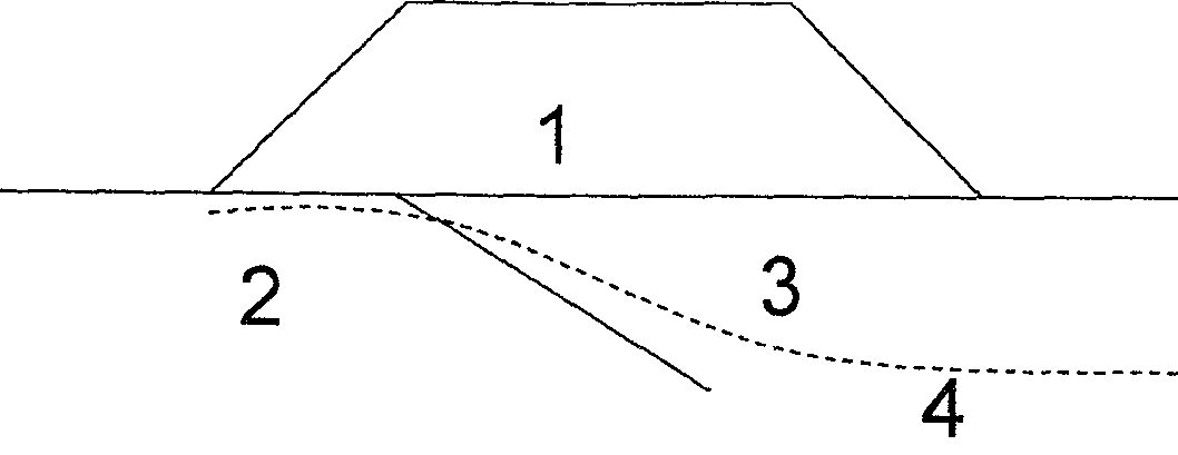
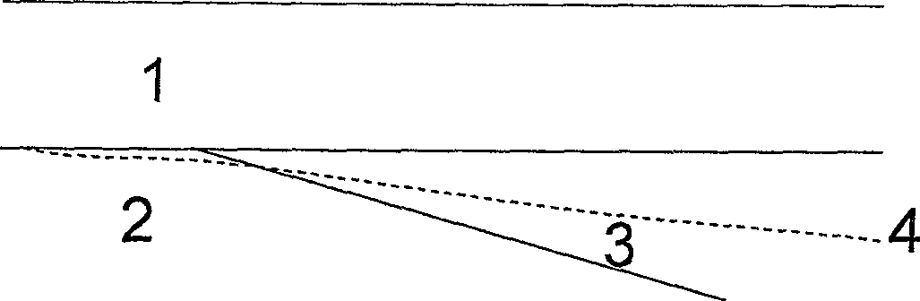
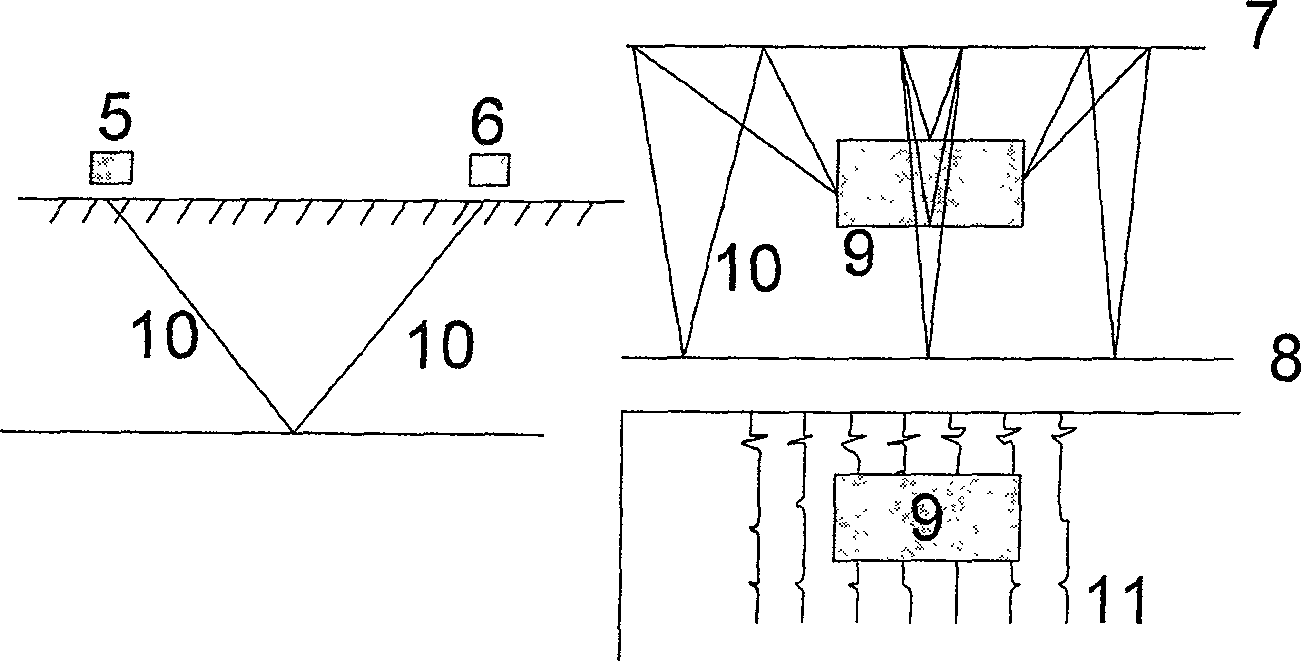
[0030] 1) First, select the tin foil material with a large difference in dielectric constant from the embankment soil and foundation soil. The thickness of the tin foil can reach 0.1mm, and its dielectric constant is 10 of that of the soil. 4 At this time, geological radar can be used to accurately determine the location of the road base surface and the top surface of the foundation.

[0031] 2) Lay a large area or strip of tin foil on the area to be measured. Among them, the horizontal asymmetric foundation can be laid with 20-40cm wide tin foil along the longitudinal section, and the longitudinal asymmetric foundation can be laid with 20-40cm wide tin foil near the central partition.

[0032] 3) Set or fix a point in the tinfoil paper laying area, the deformation of this point is known or can be measured. When there is a structure near the observation area, the tin foil material can be bonded to the structure. The structure is generally treated with a pile foundation. It can be ...


PUM


Abstract

The geological radar measurement complex ground deposit deformation measurement comprises the selection and tin foil with relatively big dielectric constant difference with the bank land to be tested, setting a fixed point at the tin foil area with the deformation of the point known or being able to be measured, connecting the tin foil with the structural material that usually uses pile for treatment with deposition small or zero, to get the deposit of the ground combining with the geological radar testing material, when there are structural objects close to the observation area. When the observation area is linear, it can set 1-2 deposit observation point at the local route together with the tin material, using level gage controlling the deformation of the point, combining with the general analysis of the complex ground deposit material to calculate the precise deformation of the ground.

Description

Technical field [0001] The invention is a method for testing the settlement of complex foundations, and belongs to the technical field of foundation testing in transportation engineering. Background technique [0002] In highway engineering, the deformation of the foundation under the load of the embankment is a hot spot in the process of highway construction, especially in the following three foundation conditions: figure 1 It is a horizontally uneven foundation, that is, the horizontal foundation along the embankment has a certain slope, and the road built there will produce large deformation on the side of the weak foundation (slope instability or transverse cracks), which will affect the use of the embankment Features; figure 2 It is a longitudinally uneven foundation, that is, the upper soil layer has relatively large characteristics along the route (such as the section with increased soil layer change, bridge head transition section, and road section with different founda...

Claims


Application Information

Patent Timeline
Patent Type & Authority Patents(China)
IPC IPC(8): G01B15/06G01B15/00G01S13/06G01V3/12
Inventor 邓永锋羊晔刘松玉洪振舜
Owner SOUTHEAST UNIV
Why Eureka
Try Eureka